16
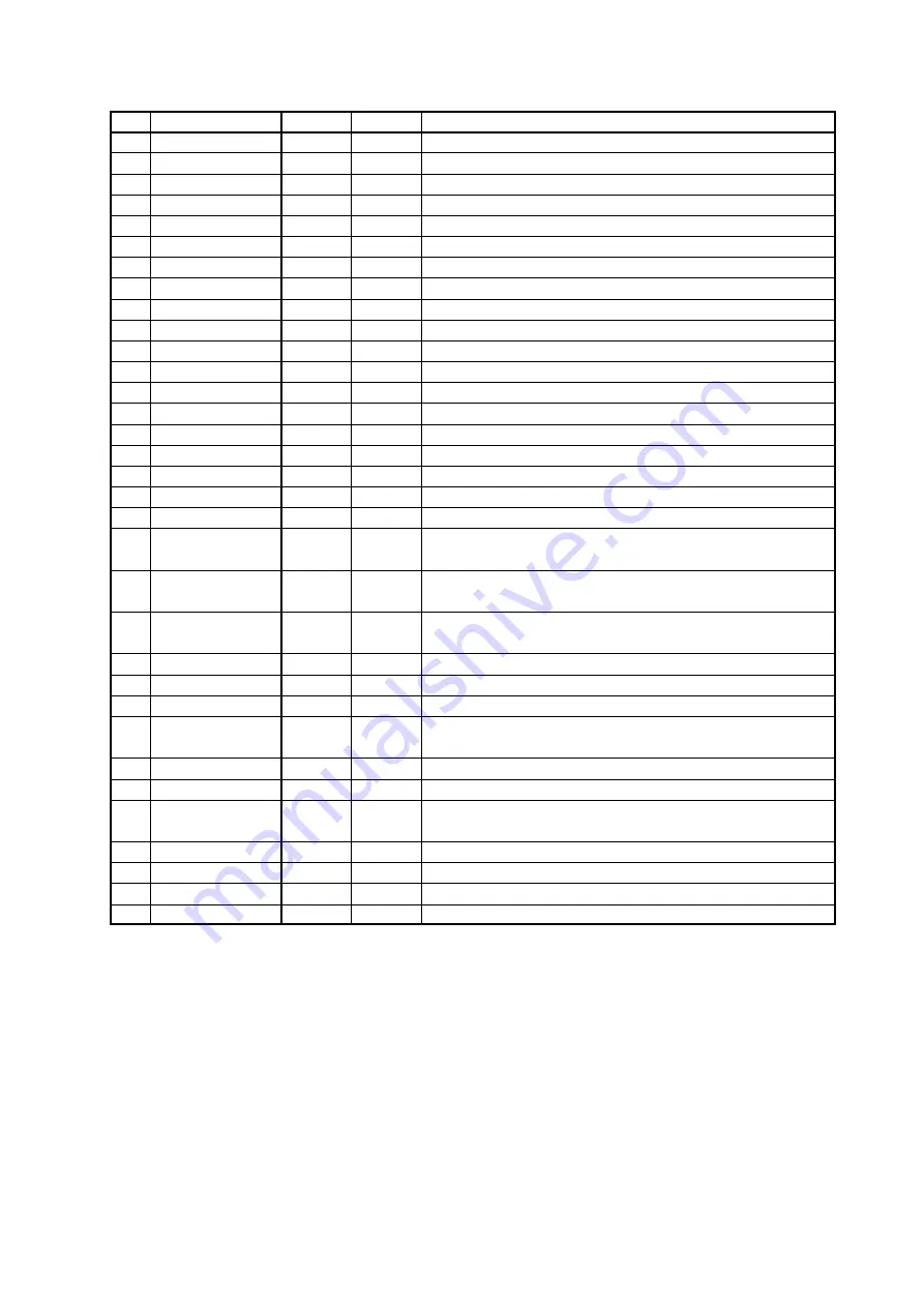
List of warnings and errors
No.
Name
Warning
1
Error
1
Description
1
Safe *
X
Input Safe activated
2
Control signal
X
Value of control signal ≤ 3 mA
(it applies to ranges 4 – 20/20 – 4 mA)
4
Torque
X
Induced torque beyond end-limit positions or disconnected torque sensor
6
Thermal protection
X
Thermal protection input activated
7
Sense of rotation
X
Reverse sense of rotation
(for CONTROL only)
8
EEPROM
X
Wrong control sum of parameters in EEPROM
9
RAM
X
Wrong control sum of parameters in RAM
10
Parameters
X
Wrong parameters in EEPROM
11
Setting regimes
X
Setting regime from push-buttons or PC
12
Torque sensor
X
Disconnected or defective torque sensor
13
Sensor 1
X
Error of sensor of position 1
(lowest stage)
14
Sensor 2
X
Error of sensor of position 2
15
Sensor 3
X
Error of sensor of position 3
16
Sensor 4
X
Error of sensor of position 4
(highest stage)
17
Calibration
X
Autocalibration not carried out
18
Torque setting
X
Wrong setting of torques
(parameters Torque O/Z 50/100 %)
19
Stroke
X
Wrong setting of stroke
(parameters Position O/Z)
21
High temperature
X
Permitted max. temperature exceeded
(parameter Temperature max.)
22
Low temperature
X
Permitted min. temperature exceeded
(parameter Temperature min.)
23
LCD internal *
X
Display of LCD internal does not communicate or not added
in parameter CAN of confi guration
24
LCD external *
X
Display of LCD external does not communicate or not added
in parameter CAN of confi guration
25 Fieldbus *
X
Module of industrial bus does not communicate or not added
in parameter CAN of confi guration
26
CAN *
X
Error of bus CAN
(short circuit, interruption, only sensor communicates)
27
Fieldbus activity*
X
Connection to industrial bus not active
28
Phase *
X
Inverse order of phases or some phase missing
29
Relay of service life
X
Service life of relay MO/MZ at CONTROL exceeded
(parameter Relay of service life)
30
Reset
X
Non-standard Reset of unit induced
(watchdog etc.)
31
ROM
X
Wrong control sum of program in ROM
32
CAN version *
X
Sensor, LCD display or module Fieldbus have incompatible
versions of fi rmware
33
Wrong command *
X
Commands Open and Close entered at the same time
34
Wrong inertia
-
-
Wrong inertia measured by autocalibration
(for autocalibration only)
35
Wrong run-down
-
-
Wrong run-down measured by autocalibration
(for autocalibration only)
41
Wrong position
X
Servo-drive is in position 25 % behind working stroke
1) Assignment can vary depending on the version of firmware of the sensor control unit.
* Applies to DMS2 only.
Memory of number of induced warnings and errors
–
For all ascertained warnings and errors, DMS2.ED uses counters of occurrence of these warnings and errors during
operation of the system.
– Values of the counters are stored to the EEPROM memory and are preserved even in case of the power supply fall-out.
– Reading of the counters is possible by means of the program for PC
– Clearing of the counters is possible by means of the program for PC with the level of authorization “SERVICE”.
Memory of recently induced warnings and errors
– DMS2.ED stores three recently induced warnings and errors to the EEPROM memory.
– Recent warnings and errors can be displayed and erased by means of the program for PC.
Summary of Contents for MODACT MO EE 52 120
Page 2: ......
Page 25: ...25 Terminal board of DMS2 Analog Terminal board of DMS2 Profbus...
Page 49: ...NOTES...
Page 50: ...NOTES...


