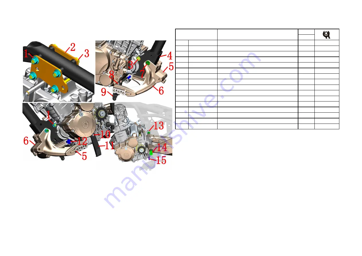
2
、
FRAME & ENGINE COMPONENT
16
CHK
ADJ
NO.
PART NO.
PART NAME
QTY
CAUTION
1
1251300-057093 Non-standard nut M10×1.5
6
65±5N.m
2
1020242-385000 ZT310
-
V Upper hanging piece
2
3
1251100-132003 Non-standard bolt M10×1.5×80
5
4
4024200-043000 ZT310
-
V bracket
1
5
ZT310
-
V front bracket of left footrest
1
6
ZT310
-
V front bracket of right footrest
1
7
1251100-137000 Non-standard bolt M10×1.5×100
1
8
1251112-003093 M6×45 hexagon flange face 9.8 bolt
1
12±1.5N.m
9
1274200-236000 ZT310
-
VX lower faring cover right support
1
10
1251112-005093 M6×75 hexagon flange bolt
1
12±1.5N.m
11
1274200-130000 ZT310
-
V left support of lower wind fairing
1
12
1251100-261000 Non
-
standard bolt M10×1.5×127 (dacromet)
1
13
1251300-067000 ZT250
-
R rear wheel hollow shaft nut
1
110N.m
14
1094200-009000 ZT310
-
V rear wheel hollow shaft
1
15
1251100-295000 Non
-
standard bolt M10×1.5×137 (dacromet)
1
Fig.3 FRAME&ENGINE
FRAME&ENGINE3
CAUTION
:
●
It is necessary to remove the seat cushion, fuel tank, side cover, pedal support, wind deflector, shift
lever, muffler, radiator and pipe, cable, air filter joint, chain, engine negative pole, etc.
●
The waste oil needs to be collected and returned to qualified institutions. It is forbidden to dump and
pollute the environment and the source of water.
●
Use the appropriate tools to support the whole vehicle to prevent accidents caused by the dumping of
the vehicle during the disassembly process; single operation is strictly prohibited.
●
All standard parts must meet the standard torque value during reassembly, and re-add the oil according
to the instructions.
PROCEDURE:
●
Front footrest bracket,wind fairing bracket
Fix the heads of bolts
⑶
and
⑺
with a 14# sleeve, and remove the 2 nuts
⑴
on the left with a 14# sleeve.
Remove the front left foot support
⑸
, and then support the front right foot support
⑹
, remove the bolts
⑶
and
⑺
and then take off the right foot support. Use an 8# sleeve to remove the bolt
⑻
and remove the right bracket
⑼
; remove the bolt
⑽
and remove the left bracket
⑾
. Install bolts
⑻
and
⑽
back to the engine. Insert the bolts
⑶
and
⑺
on the bracket back to facilitate the next step.
●
The middle part of the engine is connected with the frame and the rear fork
Bolts
⑿
and
⒂
are the shock-absorbing connecting rod components after being disassembled and then inserted
back, which is convenient for disassembly and assembly of the engine.
First use a 14# sleeve to fix the head of the bolt
⑶
at the hanger, and then use a 14# sleeve to remove the nut
⑴
. Remove the hanging piece
⑵
.
●
Disassemble the engine
Fix the head of shaft
⒁
first, and remove nut
⒀
with a 30# sleeve. After supporting the engine, one person
slightly shakes the rear fork assembly, and one person pulls out the shaft
⒁
. Continue to support the engine and
remove the bolts
⑶
and
⑺
remove the bracket
⑷
. After removing the bolts
⑿
and
⒂
, hold the engine to move
to one side, and pay attention to safety during the movement. Place the engine on a flat ground.


