


5
© Copyright 2020 Zoeller
®
Co. All rights reserved.
Installation and checking of electrical circuits and hardware should be performed by a qualified licensed electrician.
“Risk of electrical shock”
Do not remove power supply cord and strain relief or connect conduit directly to the pump.
CAUTION
Power cords, sensor cords, and float cords all must be sealed to prevent gases from the basin entering the control panel.
INSTRUCTIONS FOR CHECKING ROTATION OF THREE PHASE UNITS
It is very important that these units be connected for proper rotation. Since no rotating parts are visible without removing the pump from the pit, the rotation on 3 phase units
should be checked before installation into the pit as follows:
After the proper electrical connections are made, momentarily energize the pump observing the direction of kick back due to starting torque. The rotation is cor-
rect if the kick back is in the opposite direction of the rotation arrow. If the rotation is not correct, disconnect power and switch any two power leads. Turn power
back on and retest for proper rotation.
SENSOR CABLE
The sensor cable is the smaller cable, which contains 5 wires. The red and orange wires connect to the thermal cut-out circuit and the black and white wires
connect to the seal leak probes. The green wire is a ground connection. All 5 wires must terminate in the control panel.
The following should be noted:
(1) The thermal sensors are normally closed and mounted adjacent to the motor windings. If internal temperatures exceed a maximum limit, the pump will deac-
tivate when the red and orange wires are connected in series to the control coil of the motor starter circuit. The pump is able to restart once the motor cools
down. Continued deactivation of this circuit requires the attention from maintenance personnel.
(2) The black and white seal leak wires are connected to a 330K ohm circuit in the seal cavity, where 2 seal leak probes are housed. An indicator light will activate
whenever water is present in the cavity. Whenever the seal leak light is activated, indicating that the lower seal has failed, the pump should be removed and
serviced in order to avoid damage to the motor.
(3) The green wire shall be connected to a ground lug in the panel.
CONTROL PANELS
These pumps require a control panel. The control panel rarely requires an explosion proof rating since it is usually located outside the hazardous area. A motor
starter circuit, control circuit, and alarm circuit within the panel are standard features. Outdoor enclosure ratings and alternating relays are often required. Variable
level float switches are the most common level sensing device.
The following should be noted:
(1) Float switch connections must be intrinsically safe.
(2) Single phase units have externally mounted capacitors and starting relays. Your control panel should have provisions for mounting these starting components.
(3) The seal failure sensor and thermal sensor protection shall be incorporated into the panel.
(4) All pumps require overload protection in panel. Use with approved motor control that matches motor input in full load amperes with overload element(s)
selected or adjusted in accordance with control instructions.
(5) Hazardous Location pumps require panels that offer intrinsically safe relays and all other NEC requirements must be followed (See Article 500,501, 502 & 503
plus any others that apply.)
Pump Wiring Instructions
ZEPA0039E
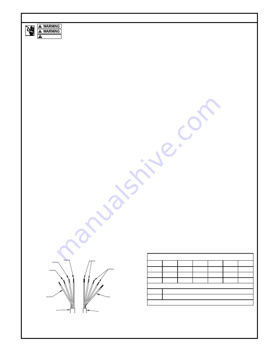
POWER AND SENSOR CORD, LEAD IDENTIFICATION
SEAL FAILURE
BLACK & WHITE
LEAD
GROUND
POWER
CORD
LEAD
SENSOR CORD
GREEN GROUND
BLACK
GREEN
RED
WHITE
SENSOR
LEADS
TEMPERATURE
RED & ORANGE
SENSOR
LEADS
“X71 SERIES GRINDER” FOUR CONDUCTOR AWG. POWER CORD SIZE
MODEL
HP
230/1PH
200/3PH
230/3PH
460/3PH
575/3PH
X7110
3
8 AWG.
12 AWG.
12 AWG.
12 AWG.
12 AWG.
X7111
5
8 AWG.
8 AWG.
12 AWG.
12 AWG.
12 AWG.
X7112
7.5
N/A
8 AWG.
8 AWG.
12 AWG.
12 AWG.
APPROXIMATE CORD DIAMETER PER GAUGE
12/4 AWG.
.64"
8/4 AWG.
.93"
NOTE: SENSOR CORD 18/5 AWG. APPROXIMATELY .44" DIAMETER.


