background image

4

© Copyright 2020 Zoeller

®

 Co. All rights reserved.

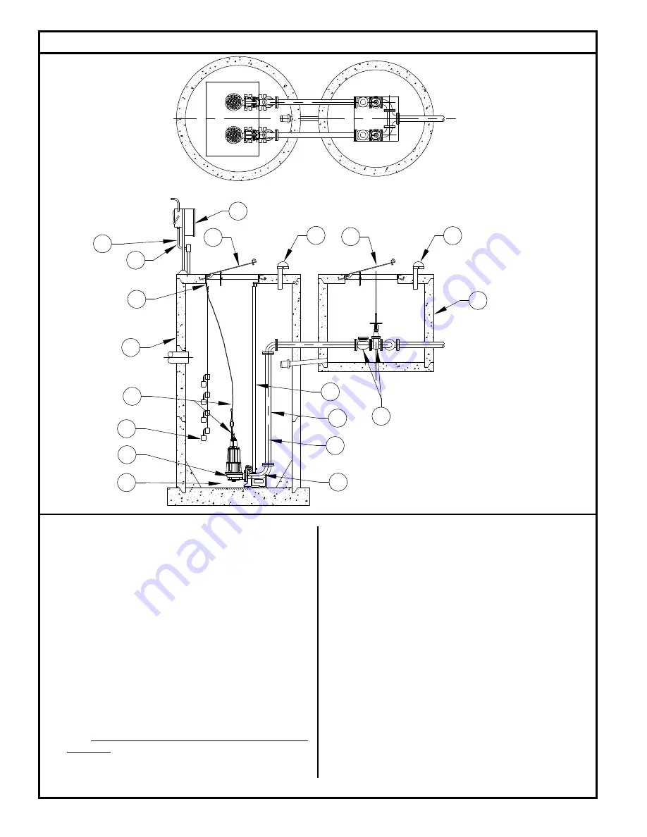
Typical Grinder Pumping System Installation

  (8)   Secure power cord to avoid entanglement with variable level 

float switch mechanism.

  (9)  

Do not

 reduce pump discharge pipe below 2” IPS size.

  (10)   Basin 

must

 be in accordance with all applicable codes


  and specifications regarding Class I, Division 1, Group C & 

D Class I, Zone 1, Groups IIA & IIB locations. Basin must be 

sized to allow a minimum 3 minute off-time between starts.

  (11)   The tethered variable level float switches must be free and not 

hang up on pump or pit peculiarities. Float switch circuits shall 

be intrinsically safe.

 (12) 

If

 a rail system is used, it should be non-sparking. Discharge 

elbow 

must

 be firmly anchored to the bottom of basin. In 

fiberglass basin, the bottom will need to be reinforced if the 

discharge elbow is used.

 (13) 

If

 a rail system is used, it should be non-sparking. The guide 

rails are 2” schedule 40 pipe for all units. Brass, stainless steel 

or galvanized steel is recommended.

  (14)   Install ring and cable for lifting pump from pit.
  (15)   Basin must be clean and free of debris after installation and 

before operation.

All installations must comply with all applicable 
electrical and plumbing codes, including, but not 
limited to, National Electrical Code, local, regional, 
and/or state plumbing codes, etc.

ZEPA0560


(1)   Electrical wiring and protection 

must

 be in accordance with the 

National Electrical Code per NEC articles 500 through 503 for 

installation in Class I, Division 1, Group C & D Class I, Zone 1, 

Groups IIA & IIB locations, and any other applicable state and 

local electrical requirements.

  (2)   Install proper full flow check and shut-off valve.

  (3)   Install proper controls (outdoor panels in ventillated areas 

require


NEMA 3R or 4X enclosure). Float switch connections shall be 

intrinsically safe.

  (4)   All installations 

require

 a basin cover to prevent debris from falling 

into the basin and to prevent accidental injury.

  (5)   Cords must be properly sealed per NEC articles 500 through 503 

for installation in Class I, Division 1, Group C & D Class I, Zone 1, 

Groups IIA & IIB locations, to prevent moisture and gases from 

entering the control panel. 

  (6)  

When check valve is installed

, drill a 3/16" diameter hole in the 

discharge pipe below the check valve even with the top of the 

pump. NOTE: The hole must be below the basin cover and cleaned 

periodically. Also a vent hole is drilled in the pump housing. Be 

sure that this hole is cleared during any servicing.

  (7)   Vent gases and odors to the atmosphere through vent pipe per 

local and state codes.

9

10

5

1

8

4

3

4

7

10

7

15

6

14

11

12

13

2

6

Summary of Contents for X71 Series

Page 1: ...1 Limited Warranty 2 Preinstallation Information 3 Electrical Data 3 Typical Sewage Installation 4 Pump Wiring Instructions 5 6 Operation 7 Maintenance 7 Service Checklist 8 Safety Instructions TO AVOID SERIOUS OR FATAL PERSONAL INJURY OR MAJOR PROPERTY DAMAGE READ AND FOLLOW ALL SAFETY INSTRUCTIONS IN THIS MANUAL AND ON THE PUMP THIS MANUAL IS INTENDED TO ASSIST IN THE INSTALLATION AND OPERATION ...

Page 2: ...ment parts For additional information pertaining to our warranty or if service cannot be obtained locally contact Zoeller Engineered Products 3649 Cane Run Road Louisville Kentucky 40211 1961 Attn Customer Service ZOELLER ENGINEERED PRODUCTS EXPRESSLY DISCLAIMS LIABILITY FOR SPECIAL CONSEQUENTIAL OR INCIDENTAL DAMAGES OR BREACH OR EXPRESSED OR IMPLIED WARRANTY AND ANY IMPLIED WARRANTY OF FITNESS F...

Page 3: ...in in detail the requirements for the installation and wiring of electrical equipment in hazardous locations 1 Not for use in acidic atmospheres 2 Do not lift carry or hang pump by the electrical cables Damage to the electrical cables can cause shock burns or death 3 Make sure there is a properly grounded connection available All pumps are furnished with provisions for proper grounding to help pro...

Page 4: ...ble electrical and plumbing codes including but not limitedto NationalElectricalCode local regional and or state plumbing codes etc ZEPA0560 1 Electrical wiring and protection must be in accordance with the National Electrical Code per NEC articles 500 through 503 for installation in Class I Division 1 Group C D Class I Zone 1 Groups IIA IIB locations and any other applicable state and local elect...

Page 5: ...rcuit in the seal cavity where 2 seal leak probes are housed An indicator light will activate whenever water is present in the cavity Whenever the seal leak light is activated indicating that the lower seal has failed the pump should be removed and serviced in order to avoid damage to the motor 3 The green wire shall be connected to a ground lug in the panel CONTROL PANELS These pumps require a co...

Page 6: ...a control panel with level control is required Follow the instructions provided with the panel to wire the system Before installing a pump check the pump rotation to insure that wiring has been connected properly to power source and that the green lead of power cord See wiring diagram is connected to a valid ground Momentarily energize the pump observing the directions of kick back due to starting...

Page 7: ...sired location of each float function Valves Dischargevalvesshouldbeplacedinthefullyopenposition Systems shouldnotbeoperatedforextendedperiodsoftimewiththedischarge valves partially closed due to damaging the valve SHUTDOWN PROCEDURES If a system is shutdown for more than six months the following is recommended Pumps If pit is to remain dry then the pump can remain in the pit With the pumpinthepit...

Page 8: ...in head and or capacity after a period or use Increase Pipe Friction Clogged line or check valve Abrasive material chemical deteriorated impeller and pump housing If the above check list does not uncover the problem consult the factory Do not attempt to service or otherwise disassemble pump Service Checklist Trouble Shooting Steps Check Voltage At If No Voltage If Voltage No 1 Line terminals in pu...

Reviews: