background image

12

© Copyright 2022. All rights reserved.

The following steps are to be completed during each 

6-month inspection.  All information collected during the 

inspection is to be recorded on the Maintenance and Service 

Report (CL0059).  Begin the inspection by recording the date, 

arrival time, weather conditions, purpose of the visit, water 

use, model number, serial number, the presence or absence 

of a septic tank, and the system owner and service provider 

information in the space provided on the report.

1.  Are any odors present? 


There should be no odor 

with the lids closed, if properly sealed.  With lids 

removed, a septic or sewer-like odor is indicative 

of poor treatment and is common immediately after 

startup due to hydrogen sulfide and other gases.  A 

well-operating system will have a musty, earthy smell 

similar to wet peat moss.

2.  Is there evidence of high water?


Typically indicated 

by a water level above the black wall markings and 

above the “0” graduation on the partition wall stickers. 

May also be indicated by debris on partition walls.

3.  Is there excess foam formation?


Foam may be 

present during an inspection.  Brown foam indicates 

bacterial buildup following startup.  White foam is 

due to detergent use. Neither is a problem if occurring 

intermittently. Detergent-based foam will often be 

accompanied by low transparency readings.

4.  Is there residue build-up on piping?

  Typically indicated 

by gray or black residue (dried foam) on aeration 

chamber piping.

5.  Is there even and vigorous bubbling? 

Bubbles surfacing 

in the aeration chamber should be even across the 

entire chamber.  If uneven, cleaning steps should resolve 

this issue.

REQUIRED WATER QUALITY ANALYSES

PART A: Clean Water Storage Chamber –


Collect samples 

from the clean water storage chamber to be used for 

the following analyses

1.  Transparency 

– 

Measures the ability of the water to 

transmit light.  Using the ladle, fill the transparency 

tube with a water sample collected from the clean 

water storage chamber.  Looking down through the 

water column, slowly drain the transparency tube 

using the valve on the flexible hose until you can 

first distinguish between the black and white colors 

on the secchi disk in the bottom of the tube. When 

the secchi disk is visible, close the valve and read 

the transparency (in centimeters) on the side.  Dirty 

water samples transmit less light and result in a lower 

transparency.  A transparency reading > 20 cm is 

preferred and 34 cm is average.  Low transparency 

may be due to a lack of biological activity as in a 

young system, a recirculation rate that is too high, 

or a system influent high in detergent concentration.  

To correct low transparency readings not caused by 

detergent, decrease the recirculation rate.  Detergent 

based problems may require consultation with owner.

2.  Scum –


Very small amounts of scum may accumulate 

in the corners on the outlet end of the system.  This 

is normal.  Scum, should not be present elsewhere 

in the clean water storage chamber unless the 

recirculation rate is too high or daily flow exceeds 

the design capacity.  If present, use ladle to transfer 

to sedimentation chamber.

3.  Sludge –


Test the sludge depth using the sampling 

device included in the maintenance kit. The bottom 

section of the sampler includes a check valve, which 

opens as the unit is lowered into the liquid. When 

the sampler has reached the bottom of the chamber 

and the liquid level equilibrated at surface level, lift 

the sampler and this action will set the check valve 

and retain the sample in the tubing.  Withdraw the 

sampler and note the depth of settled solids within 

GENERAL OBSERVATIONS

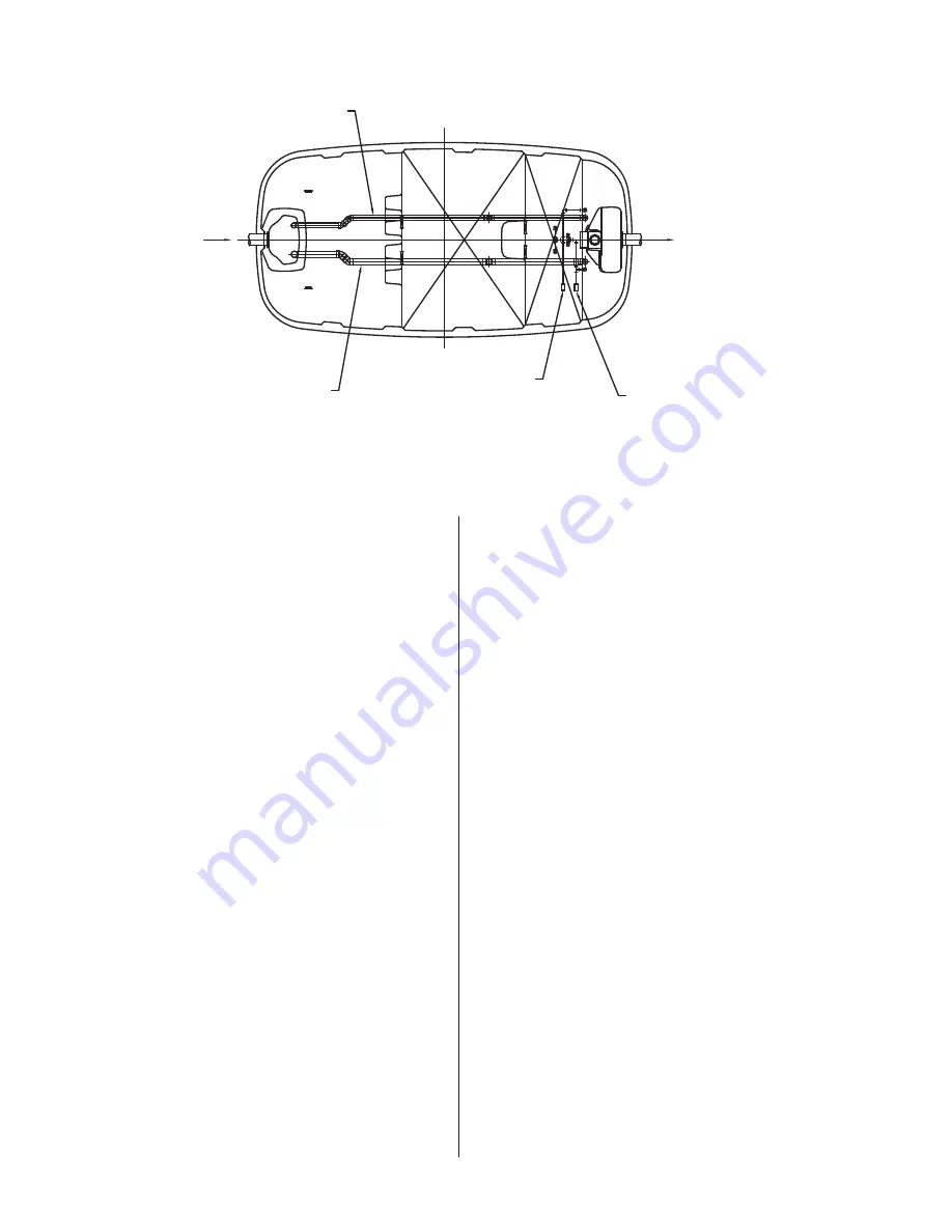
Figure 16 - Inspection details.

FUSION

®

 OPERATION AND MAINTENANCE

SK2801

INLET

3/4" AIRLINE ADAPTER

RECIRCULATION

1" AIRLINE ADAPTER

BACKWASH

2" RECIRCULATION

RETURN LINE

2" BACKWASH

RETURN LINE

OUTLET

Summary of Contents for Fusion Series

Page 1: ... years from date of purchase by the end user No allowance will be made for shipping charges damages labor or other charges that may occur due to product failure repair or replacement This warranty does not apply to and there shall be no warranty for any material or product that has been disassembled without prior approval of Manufacturer subjected to misuse misapplication neglect alteration accide...

Page 2: ...rom the liquid In the second chamber plastic media with large surface areas are used to increase contact between water and beneficial bacteria to optimize treatment A small linear air blower is used to move air oxygen into the third chamber for the aerobic process The final effluent leaving the system will have been treated to secondary quality effluent HOW A FUSION SERIES TREATMENT SYSTEM WORKS F...

Page 3: ...ous nitrogen The gaseous nitrogen then escapes to the atmosphere 3 Aeration Chamber The aeration chamber consists of an aerated upper section and a filter media lower section The chamber is filled with hollow cylindrical filter media 0 6 inch diameter 15 mm and 0 55 inches long 14 mm Biological treatment takes place on the filter media surface Aeration is continuous Residual suspended solids are c...

Page 4: ...repair them immediately Excessive water use may hydraulically overload your Fusion system and reduce its treatment efficiency Excessive water use may also overload your soil absorption field and cause failure HIGH USE WATER DEVICES The draining of hot tubs and swimming pools into your Fusion system could cause hydraulic overloading and may reduce the treatment efficiency Please drain these devices...

Page 5: ... reconnect power to either the blower or alarm panel once it has been submerged Immediately contact your authorized Fusion maintenance provider to inspect the Fusion the blower and the alarm panel Your maintenance provider will repair or replace the components as needed Fusion Series systems are compact efficient and designed to be installed in a typical residential light commercial environment Th...

Page 6: ...amp soil around perimeter of the unit as it is backfilled to stabilize the unit and to reduce settling 7 Finalize backfill with a mounded contour so that surface water is shed away from the unit Under no circumstances should surface water be allowed to accumulate around unit 8 CAUTION MAXIMUM soil burial depth over the unit is 36 inches 914 mm EXCAVATION AND INSTALLATION BACKFILLING COLD WEATHER I...

Page 7: ...er by 6 inches in height Do not install more than two riser heights together for a maximum of 12 inches burial depth Prepare risers by applying two complete circular beads of silicone or other like sealant around riser flange in order to seal risers and make the installation watertight Install the 24 inch diameter riser onto the already installed riser adapters with the provided stainless steel sc...

Page 8: ...on lines 8 Attach the small diameter black air tubing included in the blower box to barbed fitting on PVC tee Black air tubing and blower cord should be routed to the control panel through conduit Attach the black air tubing line to the air pressure sensor barbed fittings in the panel Figure 10 If air tubing is not connected to backwash and recirculation lines the panel will alarm 9 Connect the re...

Page 9: ...ncrete Volume W H Concrete Volume W H Concrete Volume W H Concrete Volume FT FT FT3 CY FT FT FT3 CY FT FT FT3 CY FT FT FT3 CY ZFL 2800 2 8 3 0 432 16 2 7 2 8 370 14 2 6 2 5 323 12 2 3 2 10 334 13 ZFL 4000 3 0 3 0 531 20 3 0 2 6 443 16 2 10 2 5 400 15 2 6 2 11 416 16 Model 24 Cover 30 Cover 36 Cover W H Concrete Volume W H Concrete Volume W H Concrete Volume FT FT FT3 CY FT FT FT3 CY FT FT FT3 CY Z...

Page 10: ...electrical codes 2 The blower should be directly wired into the alarm panel The alarm panel must be located in a dry location that is accessible for maintenance Please see the wiring diagram and instructions enclosed with the alarm panel 3 Make certain the timer within the control panel is set to the proper time The timer unit display should be set to 10 hours and the timer dial needle set to 3 6 ...

Page 11: ...ng valve control pad Set the backwash flow rate by adjusting the gray sludge transfer valve 4 Use Table 5 to determine the typical setting for each Fusion model Measuring the flow rate Measure the actual backwash flow rate at the outlet of the sludge return pipe in the first chamber the same way the recirculation flow rate is measured Adjust the gray sludge transfer valve 4 if necessary to obtain ...

Page 12: ...es 1 Transparency Measures the ability of the water to transmit light Using the ladle fill the transparency tube with a water sample collected from the clean water storage chamber Looking down through the water column slowly drain the transparency tube using the valve on the flexible hose until you can first distinguish between the black and white colors on the secchi disk in the bottom of the tub...

Page 13: ...olor remnants of digestion are often yellowish in color White sometimes present after new construction often due to drywall mud PART B Anaerobic Chamber collect samples from the outlet baffle of the anaerobic chamber to be used for the following analyses 1 Transparency A transparency reading more than 20 cm is preferred 2 Scum Should not be present unless recirculation and orbackwashrateistoohigho...

Page 14: ...aeration line after the switching valve as shown in Fig 20 Gradually open the water faucet and introduce water into the system Rotate valve 1 back and forth from the 0 to the 100 position several times to flush Turn off the water remove the water line and reconnect the airline to the blower Set valves 1 and 2 back to the appropriate positions See Recirculation Flow Adjustment pg 10 C Cleaning the ...

Page 15: ...ING 1 Odor Offensive odors are often the result of insufficient or inappropriate bacterial growth Causes may include a young or unestablished system insufficient air introduction or the addition of detrimental chemicals or poisons into the system Ensure the blower and air delivery systems are functioning Check with the homeowner regarding chemical use and disinfection habits Check all risers and l...

Page 16: ...MAINTENANCE PUMPING AS NEEDED Figure 21 Pump out procedures Step 1 Remove the scum Step 2 Remove the sludge 1 2 Sedimentation separation tank Vacuum Step 1 Remove the scum Step 2 Remove the sludge on the filter media Step 3 Remove the sludge under the media while washing the filter with tap water 1 Anaerobic filter tank Vacuum Tap water 2 3 ATTENTION Remove the scum first If you remove the sludge ...

Page 17: ...17 Copyright 2022 All rights reserved ...

Page 18: ... and pull the rubber elbow away from the discharge port of the diaphragm housing Carefully use a small flat bladed screw driver to unbond uncouple the rubber tube from the discharge port then pull it away See Figure 29 6 Next pull the diaphragm housing away See Figure 30 7 Unscrew the hex nut at the center of the diaphragm and proceed to pull the diaphragm from the magnetic bar See Figure 31 8 If ...

Page 19: ... 94 100 Weight in Pounds 2425 3748 Lids and Access 24 Diameter 4 4 Blower Information Alita AL 250 1 Alita AL 300 1 Switching Valve P N 151438 1 1 Air Line Size s 3 4 Recirculation 1 1 1 Backwash 1 1 Inlet Outlet Information Influent Invert inches 21 21 Effluent Invert inches 28 28 Inlet Outlet Pipe Size Inches 4 4 Blower Details Voltage Amps Sound dB Air Flow L min Weight Alita AL 250 120 3 7 46 ...

Page 20: ...ight 2022 All rights reserved MAIL TO P O BOX 16347 Louisville KY 40256 0347 SHIP TO 3649 Cane Run Road Louisville KY 40211 1961 502 778 2731 1 800 928 PUMP FAX 502 774 3624 Visit our website zoellerpumps com ...

Reviews: