Pelletherm V.4 LT
24
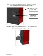
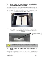
Figure 5.2. View of the connection flange for mounting of the automated pellet burner to the
boiler (the presented model is with left mounting of the pellet burner).
After the burner has been mounted the connection screws must be tightened equally, in order to
ensure proper sealing between the flange and the boiler body.
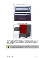
Figure 5.3. View of mounted pellet burner from series “GP xx sc”.
Threaded studs for
mounting of a pellet
burner “GP xx sc” to the
boiler
Side flange for mounting
of the pellet burner
Summary of Contents for GP ** sc
Page 46: ...Pelletherm V 4 LT 46...
Page 48: ...Pelletherm V 4 LT 48...


