Pelletherm V.4 LT
28
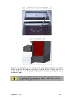
This cover is equipped with isolation panel, designed for operation at high
temperatures in the boiler’s combustion chamber.
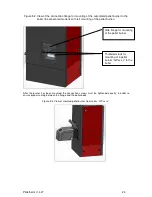
Figure 5.10. Directing cover over the boiler’s combustion chamber.
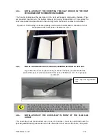
Figure 5.11. The directing covers of the flue tract of the boiler are correctly positioned.
These covers are not the same and their positions must not be changed.
5.4.10.
CONNECTING THE AUTOMATED PELLET BURNER FROM SERIES “GP XX
SC” TO THE BOILER.
Electrical connectors are installed on the rear side of the boiler’s side cover
panel. There are connectors to power supply, to burner and to room
thermostat. Depending on whether it is with left or right burner mounting, the
connectors are positioned on the same boiler cover side as the burner.
These connectors are equipped with a component that protects from
unintended disconnection. The component has to be manually freed in order
to disconnect the couplings.
5.4.11.
INSTALLATION OF THE FUEL TRANSPORT AUGER TO THE BURNER’S
MAIN MODULE.
The fuel transport auger must be installed in accordance to the information presented in the
pellet burner from series “GP xx sc” manual book.
During installation of the auger all requirements presented in the burner manual book must
be observed.
Directive cover above the
heat exchanger
Summary of Contents for GP ** sc
Page 46: ...Pelletherm V 4 LT 46...
Page 48: ...Pelletherm V 4 LT 48...


