


INSTRUCTION MANUAL CENTRAL COMMAND STATION MX10 Page 19
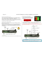
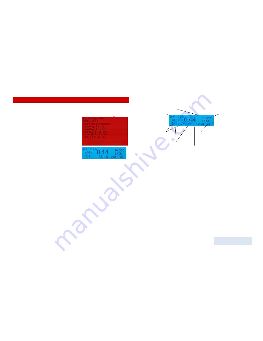
Track signal statistics
(number of
sent command packets per sec);
xx DCC
= only DCC packets
xx MM
= only MM packets
.
xx/yy D/M
= DCC and MM
RailCom - statistics
(number
of received notifications as
feedback to DCC commands).
CAN Bus - statistics
(number of CAN packets);
CAN xxx E
= number of CAN packets per sec
**)
C xxx E yy%
= number and percentage of errors
Measured temperature
of the PCB (Celsius)
(Flash drive)
8.
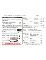
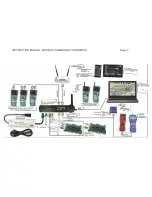
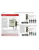
Usage and operating elements
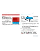
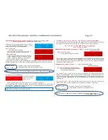
The MX10 automatically starts with a starting sequence when connected to the power supply unit, which
takes a few seconds.
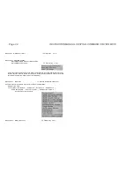
The boot screen
RED
shows a booting protocol. If the
MX10 is connected to the LAN and has a valid IP address,
the screen shows “LAN link active”. If it is connected via
USB port, it shows “VCom Link active”.
In case the MX10 is connected to the LAN and via USB
port, the LAN prevails -
USB therefore is inactive!
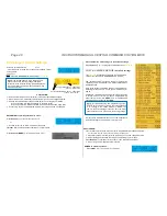
After the booting sequence, the MX10 changes to the
normal
BLUE
screen. It shows the currently measured
voltage and current values on both track outputs as well as
some communication data (DCC, CAN,...). The very big
number (in the middle) shows the current current con-
sumption on track 1.
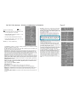
Depe
nding on the configurations for START UP CURRENT and START UP TIME (see “voltage and
current settings
”), the voltage is started up faster or slower, which, in turn, depends on capacitors in the
vehicles that may be loaded. The start up process can be observed on the screen.
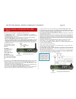
8.1
The normal screen on the MX10
AOS inputs/outputs
, shows the status
of all 14 connections.
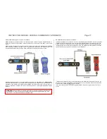
Voltage and current
on
Input “
DC in”
, i.e. of the
power supply unit, which
supplies the MX10 and the
whole layout (“primary
supply)
*)
Voltage and current
on
output
track 1:
(DC output S1 included).
Voltage and current
on output
track 2
(DC output S2 included).
*)
The power indicator for the “DC-in” input (power supply unit) is not determined by measurement,
but derived from the output currents (track outputs 1, 2, as well as the 12V and 30V outputs and
the internal consumption of the device) taking into account the efficiency of the voltage converter.
This is especially relevant when estimating, if the power supply unit still provides enough power
reserves.
**)
Sporadic flaring-
up of the letter “E” shows singular errors on the CAN bus, which can occur
when plugging in/unplugging devices, but they usually do not make problems. With more than
10 errors per second, the screen swi
tches to “E” with the percentage of the received damaged
packets (in relation to the overall number of packets that are displayed behind “C”); if the per-
centage is a few percent or higher, this may point to bad transmission quality on the CAN bus
(e.g. because of long, badly connected cables).
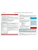
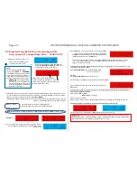
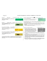
Leaving the “normal screen” is possible by the following events:
Insert flash drive (with the files to update the MX10 and/or the decoder software or to load
sound into the root directory)
screen
TURQUOISE
Flash drive options
(Chapter 8 / 8.8 & 8.9)
(Rotating fast)
Screen
YELLOW
:
VOLT & AMPERE Settings
(8.2).
Press rotary knob LONG (2 sec)
screen
RED
:
Broadcast Stop (BCS) and power OFF
(8.3).
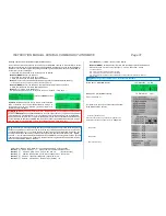
Press
Button
3
(
)
screen
GREEN
:
“BaseCab”, Driving and programming
(8.4, ..., 8.7)
Press
button 2 (MENU)
screen
GREY
:
MENU for operating the MX10 (chapter 8.8).
Press
Button
1
(
)
screen
GREY
:
AOS (automatic operation sequences)
Overcurrent
on a track
screen
RED
:
OVC on track 1 or 2 (other one runs as usual)
(8.3)
Undervoltage
From input (power supply unit)
screen
RED
:
Power supply not enough.
Overview over
applications:
see
chapter 8.8 - MENU


