


Page 22 INSTRUCTION MANUAL CENTRAL COMMAND STATION MX10
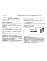
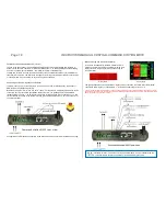
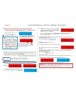
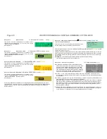
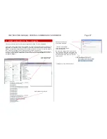
Press rotary knob LONG (4 sec)
or double-press within 1 sec
Screen colour changes to
RED
, STOPP&OFF -
screen:
Broadcast Stop (BCS) on track 1
, nor-
mal operation on track 2 stays active.
NOTE:
Press rotary knob VERY LONG
(8 sec)
SYS OFF = STANDBY:
In “STANDBY” all outputs are turned off,
i.e. track and DC outputs, as well as the
supply wires on the bus cables. There-
fore, also the controllers are turned off.
ATTENTION:
the command station
itself stays active in “STANDBY”; the
controller part stays active. For safe-
ty reasons, “STANDBY” shall only be
used under supervision.
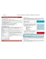
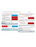
8.3
Broadcast Stop (BCS, BCSe), turn off voltage (OFF),
Overcurrent (OVC), Undervoltage (UND)
– STOPP & OFF
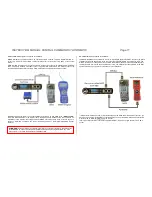
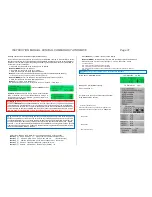
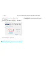
Starting point: Normal screen
BLUE
State of track 1: BCS - Broadcast Stop
Preview on state after pressing T1 - OFF
State of track 2 (below): normal operation stays.
Changing state with T2 - BCS
The STOPP & OFF screen can also be reached via the menu point STOPP & OFF (chapter 8.8). If this
screen is called up from the menu, both track outputs are in operating state ON. To stop track 1,
but-
ton
1
(
) has to be pressed, and for track 2,
button 2 (MENU).
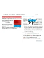
Broadcast Stop (BCS), voltage off (OFF), can also be controlled and cancelled via controllers, and are
shown on their displays and and on the MX10’s display.
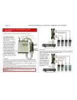
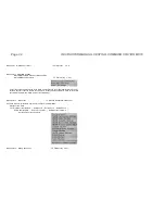
Button 1
track-1
The states of track 1 and track 2 (independently
or with individual keys each) can be switched cyclical:
Button 2
track 2
BCS
(Broadcast Stop)
OFF
(voltage off)
ON
(normal operation)
BCS
OFF
etc.
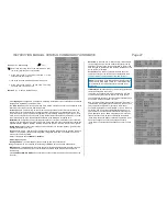
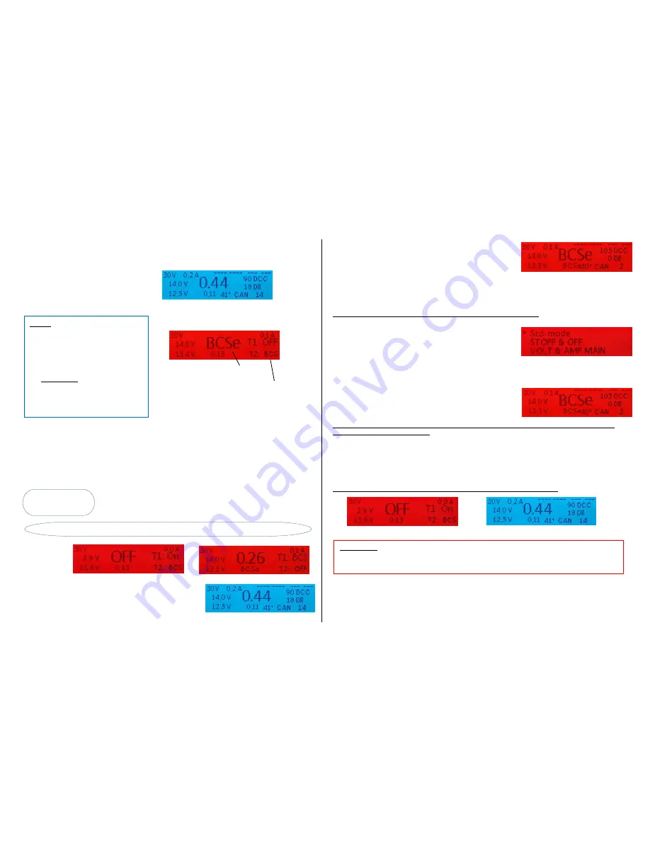
Example:
As soon as both track sections are turned on again
(after 2
sec) it switches automatically to normal operation, normal
screen
BLUE
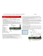
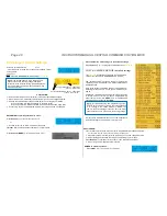
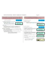
Press
button 3
(
)
to “not so normal” *) normal screen
RED
*)
“not so normal” means that BCS and OFF operations
are
NOT
cancelled and therefore, the usually blue screen
is
RED
; the trains on track 1 do
NOT
start.
This “not so normal screen” is used to reach AOS, MENU and LOCO with the buttons 1, 2, 3 (as
in the “real” normal screen). This way, complete operation is possible, also if one of the track
outputs is turned off or stopped.
To get back to the “STOPP & OFF” screen from the “not so normal screen”: (to switch the states of track
1 and track 2 with buttons 1 and 2)
Press
button 2 (MENU)
shows MX10 MENU
RED
(Cursor on STOPP & OFF)
and again:
Press
button 2 (MENU)
normal screen
BLUE
or
Press rotary knob LONG (4 sec)
STOPP & OFF screen
RED
Now, the states of track 1 and 2 can be switched cyclically in-
dependently.
If you change from the “not so normal screen” via pressing the rotary knob long (4 sec) in the STOPP &
OFF screen, consider the following:
State of track 1:
ON
BCS
BCSe
/
OFF
no change
State of track 2: no change
Means: if track 1 is ON, it is set to (Broadcast Stop) BCSe when entering into the stopping operation.
Cancelling broadcast stop started by the rotary knob; going back to normal screen:
Press rotary knob
track 1 BCSe =
ON
and back to normal screen
BLUE
T1
T2
ATTENTION:
This is only valid if the rotary knob was pressed LONG in the normal screen to start
broadcast stop (track 1 = BCSe and track 2 = ON) or if this state is called up (again) manually in the
STOPP & OFF screen (by repeatedly pressing button T1 and T2).


