


9.10
IO Setup
IO Setup
IO Setup
9.10.1
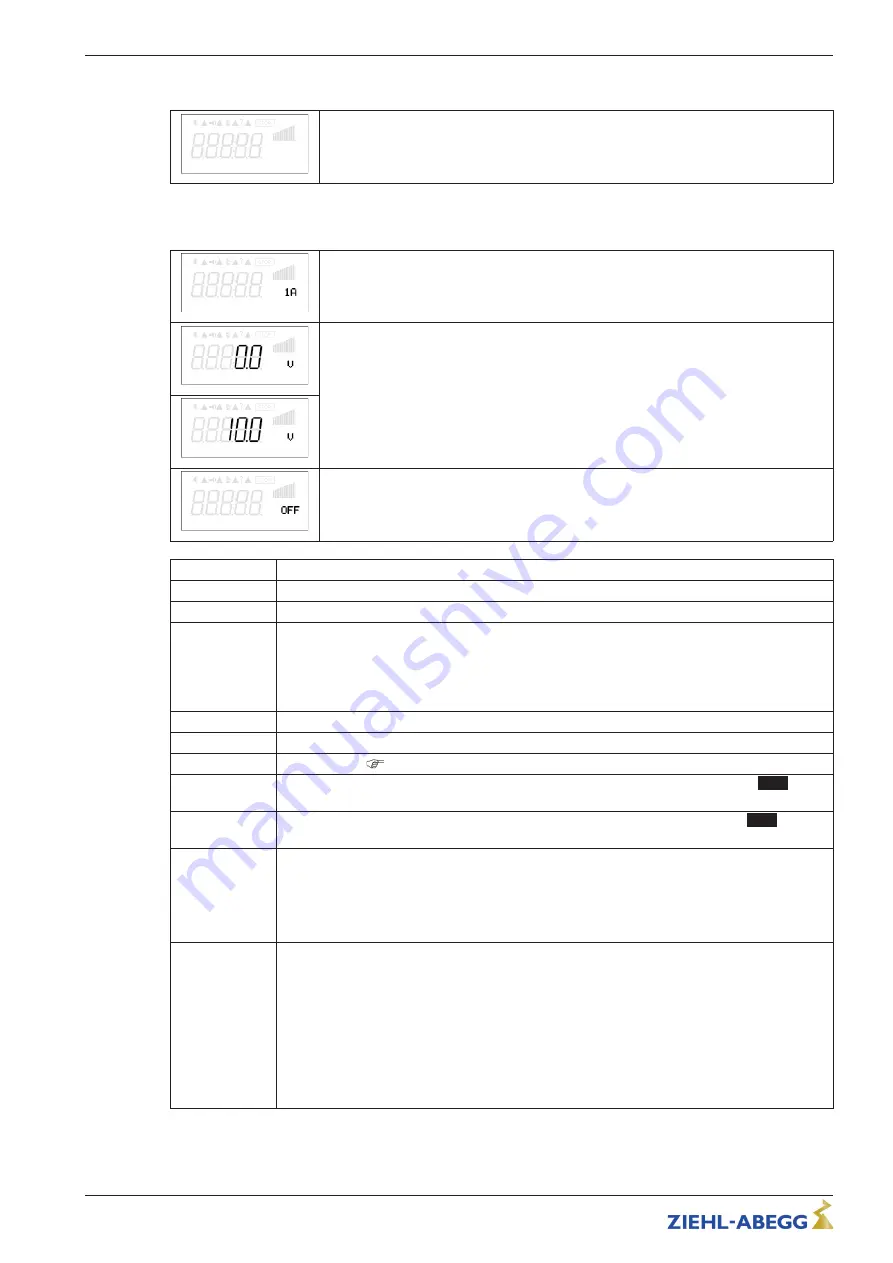
Analog-Output
“
A
”
A Function
The analog outputs 0 - 10 V can be allocated with various functions.
Terminals
“
A
”
-
“
GND
”
= Analog Out (I
max
10 mA)
A min.
With the attitudes
“
A min
”
and
“
A max
”
the characteristic of the output voltage can be
adapted.
Setting range:
“
A min.
”
= 0 - 5 V,
“
A max.
”
= 10 - 5 V
Factory setting:
“
A min.
”
= 0 V,
“
A max.
”
= 10 V
A max.
A Inverting
With the attitudes
“
A Inverting
”
the output voltage can inverted.
Factory setting:
“
A Inverting
”
=
“
OFF
”
Function
Description
OFF
no function
1A
Constant v10 V (factory setting)
2A
Proportional the internal control of modulation with consideration
“
Min. speed
”
and
“
Max.
speed
”
setting.
•
for enable
“
OFF
”
it goes back to 0 V
•
for motor fault the output signal remains for a slave controller (
“
Master-Slave
”
combination).
3A
proportional input
“
E2
”
4A
proportional input
“
E3
”
5A
Group control (
Controller Setup - second group)
6A
Control output 2 increasing modulation at actual value > Set = cooling (only mode
2.03
temperature controller with additional functions).
7A
Control output 2 incresing modulation at actual value < Set (Heating) only mode
2.03
temper-
ature controller with additional functions).
9A
ECblue = speed output
ratio: actual speed / rated speed (for 10 V actual speed = rated speed)
Icontrol / Fcontrol Basic
Proportional to the output frequency
10A
Operating indicator
ECblue:
•
Output 0 V @ Speed < 50 rpm
•
Output 10 V @ Speed > 70 rpm
Icontrol / Fcontrol Basic
•
Output 0 V @ Speed < 5 Hz
•
Output 10 V @ Speed > 7 Hz
Operating Instructions
AM-PREMIUM(-W)
–
model series
Programming
L-BAL-E095-GB 1618 Index 006
Part.-No.
45/90


