System Installation
2-3
System Installation
Chassis Installation
Be sure to locate the system near all external equipment to which you will connect it. Cable
lengths and physical/electrical characteristics are critical to system operation, especially for
data signal interfaces. Generally, higher data rates require shorter cables than lower data rates.
Also, you must use T1-grade cables for all system connections to those networks. For best
results, use the cables supplied by your supplier when connecting your system to the
associated external facilities. For more information on system cabling, call your supplier.
2.2.3.1
Rack Installation Tips
When installing the chassis in a rack, allow at least 2 inches (5.1 cm) of space between the
chassis and the equipment in front and behind it for proper ventilation. Use the mounting
brackets and attachment hardware furnished with the chassis for this purpose, as outlined in
this chapter. If you use other mounting hardware, you may damage the chassis or circuit
boards installed in it.
Also route all cables to their destinations through conduits to enhance electromagnetic
compatibility (EMC) performance and facilitate future system troubleshooting. When routing
cables, be sure not to obstruct any chassis vents.
2.2.3.2
Tabletop Installation Tips
The chassis can be placed on a flat, smooth surface (e.g., a table) that is free of contaminants.
This surface should be capable of supporting the chassis.
If you are placing the chassis on a tabletop or other flat surface, be sure to leave enough
clearance for air circulation through the system. Make sure the chassis is accessible from both
the front and rear.
2.2.4
Installing the Chassis
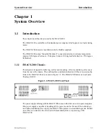
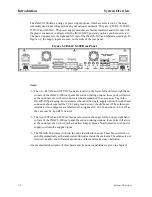
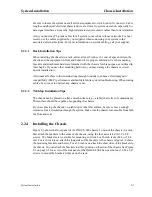
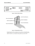
Figure 2-1 shows the front panel of the IMACS-200 chassis. To mount the chassis in a rack,
first attach the brackets to the sides of the chassis, using the four associated 10-32 x 1/4”
screws. The brackets are reversible for mounting in 19-inch or 23-inch racks (48.2 or 58.4
cm). For a 19-inch rack, attach the long sides of the brackets to the chassis (Figure 2-2 shows
the mounting brackets and holes). For a 23-inch rack, attach the short sides of the brackets to
the chassis. You can attach the brackets to either position on the side of the chassis. See Figure
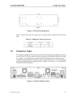
2-3 on page 2-5 for a view of the side panel of the IMACS-200.Then, use the four 12-24 x 1/4”
screws to mount the bracketed chassis on the rack.
Summary of Contents for IMA CS-200 System
Page 18: ...8 Table of Contents Model No Running Head Table of Contents...
Page 22: ...4 List of Figures Model No Running Head List of Figures...
Page 130: ...4 46 General Features Model No Running Head CPU Troubleshooting IMACS 200 General Features...
Page 148: ...5 18 WAN Ports Model No Running Head WAN port Troubleshooting WAN ports...
Page 202: ...9 14 High Speed Data Ports Model No Running Head...
Page 208: ...10 6 OHSU Ports Model No Running Head...
Page 230: ...12 16 IPR Model No Running Head IPR Configuration Screens and Settings IP Routing...
Page 264: ...A 12 System Standards and Specifications Model No Running Head IPR Server Specifications...
Page 274: ...B 10 Error Messages Model No Running Head...
Page 294: ...20 Glossary Model No Running Head Zero Code Suppression...

