


Alarm Ports
11-5
Alarm ports
Alarm port Error Messages
11.3
Alarm port Error Messages
Refer to Appendix B in this Guide for further information on Error Messages regarding these
ports.
11.4
Alarm port Troubleshooting
Alarm port problems could indicate a number of possible causes. Typically, a problem is
indicated by the loss of an incoming alarm signal on a sensor port or the lack of a contact
closure/open in response to an internal alarm. Steps designed to isolate the source of the
problem and return the port to normal operation are detailed below. When troubleshooting
Alarm port problems, you should follow this general sequence:
1. Verify that the Alarm port sensor filter (SENSOR) is set to either log or report in the
Alarm Filters Menu. This menu is accessed by selecting "Alarms" from the Main Screen
(not the Alarm port Screen), and then selecting "Filters." Column 1 lists the filter setting
(ignore, log, or report). You can change the filter setting by highlighting the item you wish
to change and pressing the <Enter> key. Use the arrow keys to highlight a new filter
setting and press the <Enter> key again. If you are satisfied with your selections,
remember to "Save" before exiting the screen. If you make any changes and then attempt
to exit the screen without saving, you will be prompted "Ok to lose changes (y/n)?" You
must select "y" or "n". If you select "y", any changes will be lost and all selections will
revert to the last saved state.
2. On the Alarm port menu, verify that the switch/sensor in question is set to active (actv).
If set correctly and the problem is with a switch (contact), go to step 3. If the problem is
with a sensor, go to step 5.
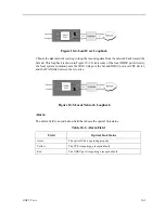
3. Verify that the amphenol cable is connected correctly to the Voice port. At a
cross-connection point between the Alarm port and the external “scan point”, open the
circuit under test. Connect a Volt-Ohmmeter set to read resistance across the Alarm port
contact in question. If no alarm of the type (Major, Minor or Any) that the contact is
programmed to act upon is present, and it is a normally open (NO) contact, the meter will
read infinite resistance. If you are testing a normally closed (NC) contact, the meter will
read 0 ohms resistance.
4. Generate an alarm of the type (Major, Minor or Any) that the contact is programmed
to act upon. The Volt-Ohmmeter should detect a resistance change from 0 to infinite or
infinite to 0, depending on the type of contact (NO or NC). If no change is detected, the
switch port may be defective.
5. Verify the RJ45 cable is connected correctly to the Alarm port. At a cross-connection
point between the Alarm port and the external equipment, open the circuit under test.
Connect a short across the Alarm port sensor input in question. A SENSOR alarm should
be reported. If no alarm is reported, the sensor port may be defective.
Summary of Contents for IMA CS-200 System
Page 18: ...8 Table of Contents Model No Running Head Table of Contents...
Page 22: ...4 List of Figures Model No Running Head List of Figures...
Page 130: ...4 46 General Features Model No Running Head CPU Troubleshooting IMACS 200 General Features...
Page 148: ...5 18 WAN Ports Model No Running Head WAN port Troubleshooting WAN ports...
Page 202: ...9 14 High Speed Data Ports Model No Running Head...
Page 208: ...10 6 OHSU Ports Model No Running Head...
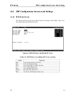
Page 230: ...12 16 IPR Model No Running Head IPR Configuration Screens and Settings IP Routing...
Page 264: ...A 12 System Standards and Specifications Model No Running Head IPR Server Specifications...
Page 274: ...B 10 Error Messages Model No Running Head...
Page 294: ...20 Glossary Model No Running Head Zero Code Suppression...


