The Zeroplus Logic Analyzer
Installation Guide
The Zeroplus Logic Analyzer Installation Guide
Page 24
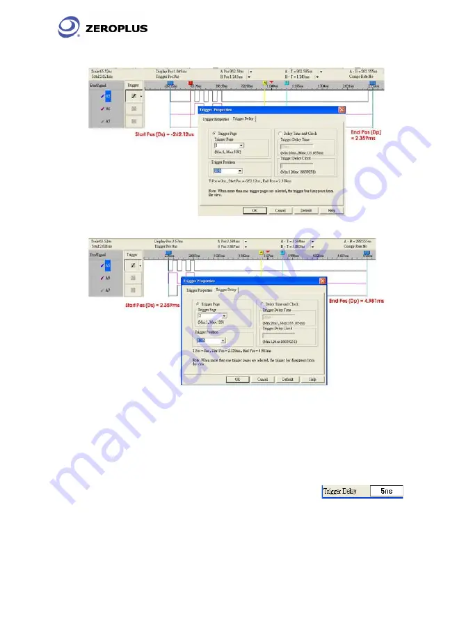
Fig 3-9 – Trigger Page
Fig 3-10 – Trigger Position
Fig 3-11 – Trigger Position and screen
2. Delay Time and Clock
Click the Delay Time and Clock, then type the numbers into the column of the
Trigger Delay Time or type numbers into the Trigger Delay Clock at the
“Trigger Delay” page of the Trigger Properties dialogue as 0 and Fig 0. Or
type the numbers into the column of Trigger Delay
on
the Tool Bar. The system will display the wave start.
Tip:
The formula of Delay Time and Clock is “ Trigger Delay Time = Trigger
Delay Clock * (1/ Frequency)”.
Summary of Contents for LAP-321000U-A
Page 1: ......


