background image


MAXinBOX FC 0-10V FAN


http://www.zennio.com


Technical Support: 

http://support.zennio.com 


30 


30 

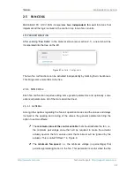
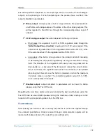
stated  before,  using  the  Test  Off  mode  does  not  require  any  special  action, 

while  switching  to  the  Test  On  mode  does  require  long-pressing  the 

Prog./Test button. 


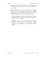
Manual  Control  Lock

:  unless  the  above  parameter  has  been  “Disabled”, 

enabling the Lock Manual Control parameter will provide a runtime procedure 

for  locking  the  manual  control.  When  this  checkbox  is  enabled,  object 

Manual Control Lock

” turns visible, as well as two more parameters: 


Value

:  defines  whether  the  lock/unlock  of  the manual  control  should take 

place respectively upon the reception (through the aforementioned object) 

of values “0” and “1”, or the opposite. 


Initialization

: sets how the manual control should remain after the device 

start-up  (after  an  ETS  download  o

r  a  bus  power  failure):  “Unlocked”, 

“Locked” or, by default, “Last Value” (on the very first start-up, this will be 

Unlocked). 

Summary of Contents for MAXinBOX FC 0-10V FAN

Page 1: ...MAXinBOX FC 0 10V FAN 2x Two Four Pipe Fan Coil Controller with 0 10 VDC Fan Control Signal USER MANUAL ZCL FC010F Application Program Version 1 5 User Manual Version 1 5 _a www zennio com...

Page 2: ...up and Power Loss 8 2 Configuration 9 2 1 General 9 2 2 Inputs 11 2 2 1 Binary Input 11 2 2 2 Temperature Probe 11 2 2 3 Motion Detector 11 2 3 Binary Outputs 13 2 4 0 10V Analogue Outputs 14 2 5 Fan...

Page 3: ...MAXinBOX FC 0 10V FAN http www zennio com Technical Support http support zennio com 3 Annex II Operation Examples 36 Annex III Communication objects 38...

Page 4: ...Changes in the application program Heartbeat functionality added Master Light functionality added Fan speed manual control Optimisation of the Fan Coil Binary Inputs Individual Digital Outputs Analog...

Page 5: ...h can be enabled and configured independently which lets the integrator combine them as desired to control up to 2 two pipe or four pipe fan coil units At a glance the most outstanding features of MAX...

Page 6: ...evices one of which acts as a general lamp and the others as secondary lamps Heartbeat or periodical still alive notification The MAXinBOX FC 0 10V FAN application program focuses on the control of fa...

Page 7: ...re described next Test Prog pushbutton 8 a short press on this button sets the device into the programming mode making the associated LED 5 light in red Note if this button is held while plugging the...

Page 8: ...conds before MAXinBOX FC 0 10V FAN is ready External orders will not be executed during this time but afterwards Depending on the configuration some specific actions will also be performed during the...

Page 9: ...quired functionality ETS PARAMETERISATION Figure 2 General screen Once activated Inputs Binary Outputs 0 10V Analog Outputs Fan Coils Logical Functions Thermostats Manual Control enabled by default an...

Page 10: ...t Periodical Alive Notification this parameter lets the integrator incorporate a one bit object to the project Heartbeat Object to Send 1 that will be sent periodically with value 1 to notify that the...

Page 11: ...0 10V FAN product section at www zennio com 2 2 2 TEMPERATURE PROBE Please refer to the Temperature Probe user manual available under the MAXinBOX FC 0 10V FAN product section at www zennio com Note...

Page 12: ...y being connected to the functionality may differ slightly Therefore please refer specifically to the aforementioned user manual Motion detectors with references ZN1IO DETEC and ZN1IO DETEC N are not...

Page 13: ...any other MAXinBOX actuators Note that they all work independently although it is possible to group them as required for example to pen a gate valve when another one closes through joint group addres...

Page 14: ...o control the fan speed of one fan coil unit One on board LED indicator is offered per output to show the status it will remain off while the output signal is 0V and on while it is 10V Under intermedi...

Page 15: ...the bus after receiving a new voltage setpoint and when the output status changes due to a lock order The following parameters can be configured from the corresponding tab Figure 7 0 10V Analog Output...

Page 16: ...hen selecting On the desired Output Value needs to be configured in terms of percentage Send Status when marked the status object will be sent to the bus with a customisable Delay from 0 to 600 ds 0 t...

Page 17: ...COIL x Each fan coil function requires setting some general parameters and optionally some advanced parameters All of them are described next 2 5 1 1 GENERAL Among other options regarding the fan coi...

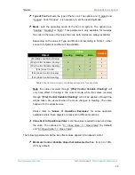
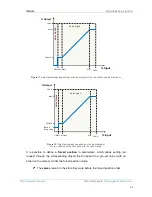
Page 18: ...his is called Offset 2 in Figure 9 Figure 9 Output percentage value depending on the input setpoint and the offsets ETS PARAMETERISATION The Configuration screen see Figure 10 is accessible by default...

Page 19: ...ve Control x x x FCx Valve Control Cooling x FCx Valve Control Heating x Table 1 Fan Coil communication objects depending on the Type and Mode Note the values received through FCx Control Variable Coo...

Page 20: ...minimum time the device should wait between the order to close the valve under the old mode and the order to open the valve in the new mode The allowed values are 0 to 600 ds 0 to 3600 s 0 to 1440 min...

Page 21: ...valve closed It is possible to define a forced position in parameters which allows setting on request through the corresponding object the fan speed to a pre set value with no action on the valves Und...

Page 22: ...red Finally it is possible to enable fan speed manual control during the normal operation and when the valve is closed in cooling mode There are the following objects related to this functionality ena...

Page 23: ...y default the fan coil turns on off when receiving a 1 or 0 through the object FCx On Off respectively The state of the fan coil can be obtained by reading the FCx On Off Status communication object a...

Page 24: ...ol is deactivated when sending disable through the object FCx Manual Fan Control but also when the mode switches or when turning off the fan coil Return to Automatic Mode after a Period of Time when e...

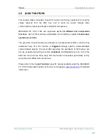
Page 25: ...consecutive operations each one The execution of each function can depend on a configurable condition which will be evaluated every time the function is triggered through specific parameterisable com...

Page 26: ...MOSTATS MAXinBOX FC 0 10V FAN implements two Zennio Thermostats which can be independently enabled and fully customised Please refer to the Zennio Thermostat specific manual available under the MAXinB...

Page 27: ...spond to user presses from the start On the contrary switching to the Test On mode unless disabled by parameter needs to be done by long pressing the Prog Test button for at least three seconds until...

Page 28: ...is long pressed the actuator will start increasing or decreasing the fan speed progressively as long as the button is being held The direction of the regulation with every new long press will be downw...

Page 29: ...they are binary or analogue outputs The lock timer alarm and scene functions will not work while the device is under the Test On mode but will be taken into account when leaving the Test On Mode Stat...

Page 30: ...provide a runtime procedure for locking the manual control When this checkbox is enabled object Manual Control Lock turns visible as well as two more parameters Value defines whether the lock unlock...

Page 31: ...up to the integrator the decision of what to send to the KNX bus in both cases a shutter order a thermostat setpoint or mode switch order a constant value a scene Only the trigger object and the twel...

Page 32: ...the value 0 1 or 0 1 being the latter the default option that will trigger when received through ML Trigger the master action the general switch off or the courtesy switch on General Switch Off Delay...

Page 33: ...eters available here are entirely analogous to those already mentioned for General Switch Off However in this case the names of the objects start with ML Courtesy Switch On On the other hand sending s...

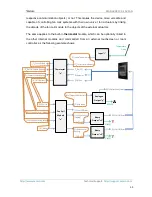
Page 34: ...control the fan coil module together with the built in outputs modules by grouping their FCx On Off FCx ControlVariable Cooling FCx ControlVariable Heating FCx Mode Fan Coil Module x Analogue Output y...

Page 35: ...d commanded from an external touchscreen or room controller as the following example shows Fan Coil Module x FCX FanSpeed FCX On Off Status FCX ValveControl Cooling FCX On Off FCX ControlVariable Cool...

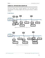
Page 36: ...0 Figure 17 On Off 4 pipes initial value 0 On On status FC MODULE t Off Valve Control Close Fan Speed 0 tdeactivation heating Off Heating mode Control 0 Off status On Off Valve Control Close Fan Speed...

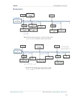
Page 37: ...et1 Fan Speed 0 tdeactivation cooling Valve Control Close Valve Control Open Fan Speed V 0 Cooling Valve Control Close Fan Speed Vp Cooling status Heating status tchange mode tactivation heating tdeac...

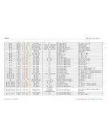
Page 38: ...tes O C T R DPT_Value_Temp 273 00 670760 00 Tx Effective Temperature Effective Control Temperature 8 38 1 Byte I C W DPT_HVACMode 1 Comfort 2 Standby 3 Economy 4 Building Protection Tx Special Mode 1...

Page 39: ...1 Tx Control Variable Heat PI Control PWM 31 61 1 Bit O C T R DPT_Switch 0 1 Tx Additional Cool Temp Setpoint Band 1 32 62 1 Bit O C T R DPT_Switch 0 1 Tx Additional Heat Temp Setpoint Band 1 33 63 1...

Page 40: ...138 157 162 167 186 191 196 1 Bit O C T R DPT_Switch 0 1 Ix Cx Detection State Binary Binary Value 100 105 110 129 134 139 158 163 168 187 192 197 1 Bit I C W DPT_Enable 0 1 Ix Cx Enable Channel Acco...

Page 41: ...ep 0 1 Ix Short Press Stop Step Shutter Switched Switching of 0 1 Stop Step Up Down 4 Bit C T DPT_Control_Dimming 0x0 Stop 0x1 Dec by 100 0x7 Dec by 1 0x8 Stop 0xD Inc by 100 0xF Inc by 1 Ix Short Pre...

Page 42: ...1 Bit C T DPT_UpDown 0 1 Ix Long Press Move Up Shutter Sending of 0 Up 1 Bit C T DPT_UpDown 0 1 Ix Long Press Move Down Shutter Sending of 1 Down 1 Bit C T DPT_UpDown 0 1 Ix Long Press Move Up Down Sh...

Page 43: ...er Status Input 0 Top 100 Bottom 267 268 269 270 271 272 273 274 275 276 277 278 279 280 281 282 283 284 285 286 287 288 289 290 291 292 293 294 295 296 297 298 1 Bit I C W DPT_Bool 0 1 LF 1 Bit Data...

Page 44: ...able 1 Enable 363 378 1 Bit O C T R DPT_Switch 0 1 FCx Manual Fan Control Status 0 Disabled 1 Enabled 364 379 1 Byte I C W U DPT_Scaling 0 100 FCx Control Variable Cooling 0 100 365 380 1 Byte I C W U...

Page 45: ...witch On Binary Object Switch On Sending 405 1 Byte C T DPT_Scaling 0 100 ML Courtesy Switch On Scaling 0 100 406 1 Byte C T DPT_SceneControl 0 63 128 191 ML Courtesy Switch On Scene Scene Sending 407...

Page 46: ...n and send us your inquiries about Zennio devices http support zennio com Zennio Avance y Tecnolog a S L C R o Jarama 132 Nave P 8 11 45007 Toledo Spain Tel 34 925 232 002 www zennio com info zennio c...

Reviews: