ZENA mobile welding system -- Operators Manual -- Series 150 & 200 Welders
18
18
Lamp 1. If Lamp 1 is NOT illuminated, go on to the next step. If Lamp 1 IS
illuminated, go to step 2.6
2.3
Check the connection of the red and black wires that provide power to the
Module. The red wire should be connected to a source of 12 volt (or 24 volt)
power. Check that power is present, and than no external fuse is blown” using a
meter or test light. The black wire should be connected to the vehicle’s chassis
ground. Use your meter to insure that a proper electrical connection to chassis
ground exists. If power and ground connections are OK, but Lamp #1 is still not
illuminated, go on to the next step. If you found and corrected an improper
connection, and if Lamp #1 is now illuminated, go to step 2.8
2.4
The Module’s internal solder-in fuses are covered with a silicone
adhesive/sealant. Carefully remove the silicone to expose the fuse leads.
Then, using a test lamp or a volt meter
with
a
sharp
test
probe
end
, check for
the presence of power at the end of the 2 amp. fuse which is closest to the point
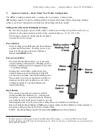
where wires enter/exit the Control Module. The 2 amp. fuse (one of two fuses
in the Control Module) is the “top” or upper fuse when viewing the Control
Module from above, with the wires going to and from the Control Module on the
viewer’s left. (SEE CONTROL MODULE DIAGRAM ON PREVIOUS
PAGE) If you do not have a test lamp or meter, go to step 2.9.
If power is
not
present at the end of the 2 amp. fuse, power is not getting to the
Control Module. In this case, it is likely that a problem exists at the point of
connection between the red wire extending from the Control Module and the red
wire which is connected to the vehicle’s electrical system. Check wiring.
If the wiring is OK, the internal wiring of the Control Module may be at fault.
Check for continuity between the red wire extending from the Module and the
end of the 2 amp. fuse closest to the point where wires enter/exit the Module,
with your meter. If the circuit is “open”, the Module will need to be returned for
repair or replacement. Go to step 2.9. If the circuit is “closed” (“0” ohms), a
fault in the supply wiring exists -- carefully recheck wiring (red/supply wire) and
all connections.
If you found and corrected an improper connection, and if Lamp #1 is now
illuminated, or if you m12V (or +24) at the fuse, continue.
If power
is
present at the end of the 2 amp. fuse (the end
closest
to the point at
which the connection wires leave the Control Module), check for power at the
other end of the 2 amp. fuse (the end
furthest
from the point at which the
connection wires enter/leave the Control Module). If power is NOT present, go
on to the next step. If power IS present, go to step 2.6.
2.5
You have a “blown” 2 amp. fuse.
This usually indicates a failure in the Control Module itself, OR that an improper
input voltage (too high) has been present, OR that the red and black leads may
have been misconnected (reversed).
If you are able to solder, and if you have access to soldering equipment, you
may choose to replace the fuse yourself, OR you can return the Control Module
to us for repair. (Replacement fuses are available free of charge through our
technical support department.) Go to step 2.9.
2.6
While observing Lamp #2 in the Control Module (and Lamp #3 -- if you have a
WC.12RO or a WC.24RO Module), depress the Power Button on the Control


