ZENA mobile welding system -- Operators Manual -- Series 150 & 200 Welders
14
14
VIII. Trouble/Fault
Diagnosis
Your ZENA Backpak welder has been designed to be very simple to use. In addition, no expense has
been spared to insure that it is also an extremely reliable and long lasting product.
However, should you have any problems with your system, the information below will help you to use
built-in fault diagnosis tools to isolate and (often) to solve the problem that you are having.
A. System Control
Modules -- Internal Diagnostics
Both engine and welding controls are housed in compact weather tight modules which
include diagnostic circuits which can be used to help troubleshoot your welder. The
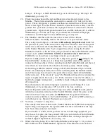
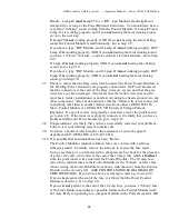
modules which are most typically used with the ZENA Backpak welder are illustrated
below. Each of the diagrams show the module with the cover removed to expose the
diagnostic indicators used with each module.
1. Welding Power Control Models
Model
WC.12B --
Location
of
Internal
Indicators
and
Fuses
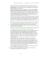
By removing 4
screws, the cover
of the Welding
Power Control
Module can be
removed.
With the cover
removed, you will
see the objects
shown in the
drawing to the
right. The four
indicators which
are labeled Lamp
#1 through Lamp
Fuse
(10 amp)
Fuse
(2 amp)
Lamp #3
(control logic
function)
Lamp #2
(control output function)
Lamp #1
(power)
Lamp #4
(speed cont.
function)
#4 will be used in the fault diagnosis steps that follow.
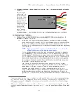
2. Automatic Engine Speed Control Module
Model
SCM.V2 --
Location
of
Internal
Indicators
and
Fuses
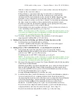
By removing 4
screws, the cover
of the Speed
Control Module
can be removed.
With the cover
removed, you will
see the objects
shown in the
drawing to the
right. The six
indicators which
are labeled Lamp
Fuse
(2 amp)
Lamp #5
(logic function/
at/above welding speed)
Lamps #2
-
4
(speed control function /
tachometer readout)
Lamp #6
(tach. signal in)
Lamp #1
(speed cont.
function)
#1 through Lamp #6 will be used in the fault diagnosis steps that follow.

