ZENA mobile welding system -- Operators Manual -- Series 150 & 200 Welders
17
17
1.4
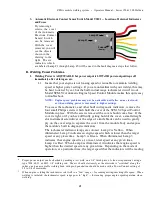
Check for the prescence of tachometer signals by disconnecting the red male
bullet connectors on the white and gray wires which exit the SCM.V2 module
from the red female bullet connectors on the white and gray wires in the
BPW150’s wiring harness, and using a multimeter to determine is there is an
AC voltage present when measuring between the two red female bullet
connectors on the white and gray BPW150 wiring harness leads. The engine
should be running for this measurement and a “correct voltage” across these .
1.4
We will now determine if the engine speed remains within the correct welding
speed range while making a test weld on a piece of 1/4” or 5/16” thick steel
plate with an 1/8” welding rod.
An assistant should be available to observe the tachometer indicator lamps --
and to listen to the engine as it drives the welding power generator.
With the engine warmed up and idling, turn the welding power control CW to
set the welding power control dial to 3/4 of maximum. Then depress, and hold,
the power button on the electrode holder.
Engine speed should increase and hold at welding speed. If the speed is
correct, Tachometer Lamps 2-4 will be cycling from green to red or green to
yellow
14
. You should not see Lamp 2 (yellow) remaining on steadily -- nor
should Lamp 4 (red) remain on steadily for more than 2 seconds. Once the
speed has increased, Lamps 1 (green) 5 (yellow) and 6 (red) should all be
illuminated.
As soon as engine speed has increased, and stabilized, attempt to strike an arc, and
begin welding while your assistant observes the tachometer lamps.
If engine speed drops dramatically at this point (possibly to a degree which
prevents welding) without instantly recovering and Lamp 2 (yellow) remains on
steadily then carburetor adjustment, throttle actuator operation, and throttle
linkage adjustment should be checked. Go to page ?? follow the carburetor
adjustment procedure, insure proper operation of the throttle actuator, and retest
the system. If the problem remains, goto Step ??
If striking a welding arc is not successful, and if all lamps indications are
normal, and if the engine is operating properly, go to the next section (Welding
Power is NOT Available).
2. Welding
Power
is
NOT
Available
2.1
Insure that the coupling between the engine and the generator is not loose or
slipping, that it is otherwise correctly installed, and properly tightened. If a
problem is found, correct the problem and re-test the system. If no problem is
found, go on to the next step in this section.
2.2
Remove the four small Philips screws which hold the cover of the Welding
Power Control in place and open the Power Control Module and Observe
12
The proper engine speed for welding is set and regulated automatically by the Automatic Engine Speed Control
Module.
13
If, at this point, the speed is too slow you will find it difficult (or impossible) to start a welding arc. If the speed is
much too high, the built in engine speed limiting circuits will be working -- preventing engine damage. But the
action of these circuits
13
may work to make arc starting less than optimal.
14
Typically, more green to red lamp activity, than green to yellow, will be noted at this point.


