34
4.3.2
Replacing the fans
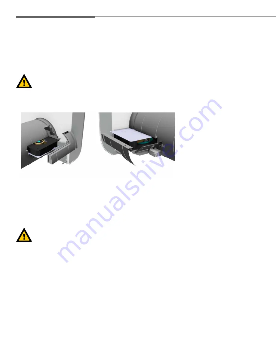
To change the fans, the unit must be completely pulled out of the wall. In doing so, proceed as follows:
1. Disconnect the CA 70 from the power supply voltage.
2. Perform steps 2. and 3. as described in 3.3.1.
3. Remove the plug on the ribbon cable from the control panel.
4. Disconnect the secondary-side low-voltage cable from the 24 V X6 terminal on the control board. Disconnect the plug
connection of the external control panel, if applicable.
5. Pull the unit completely out of the wall mounting pipe (available separately).
When replacing the fans, make sure that all the wires are disconnected prior to removal, and are reconnected per
the wiring schematic (see 3.5.4) when installing.
The fans are located in the EPP pipe, and are accessible through removal of the sealing plugs. The structurally identical fans can
be removed sideways out of the EPP pipe after the cables have been disconnected from the terminals on the control board, while
feeding the connected cables in at the same time.
6. Following the inspection, install all parts in the reverse order.
7. Restore the power supply to the unit.
4.3.3
Exchanging the control board
The control board is located in the bottom left section of the EPP housing, and becomes accessible through pulling the unit out of
the wall mounting pipe (available separately). In doing so, proceed as follows:
1. Disconnect the CA 70 from the power supply voltage.
2. Perform steps 2. to 4. as described in 3.3.1, so that you can gain access to the control board.
When replacing the control board, make sure that all the wires are disconnected prior to removal, and reconnected
per the wiring schematics (see 4.5.4) when installing.
3. Install all parts in the reverse order.
4. Restore the power supply to the unit.
INSTRUCTIONS FOR SKILLED INSTALLERS


