18 - EN
EN - 19
6.3 PI control units
The unit is equipment with several PI controls. These
PI controls are preset and can be altered when
desired.
It is recommended to keep the factory setting.
Wrong settings may cause unwanted software
responses.
PI controller
Parameter
Supply air
M04
Exhaust air
M04
Constant pressure control
M04
Sensor control
M04
Heating
M10
Cooling
M10
Bypass frost (only ComfoAir XL A)
M11
PreHeat supply
M13
PreHeat exhaust
M13
Explanation Proportional Integral controller
Proportional means the difference between the
desired and measured value enhanced by the
k-value.
Integral means providing a constant summation of
the error and keep sending more signals depending
on how long the error between desired and
measured value exists. (The time needed to get an
equivalent value as the P-action. A small time gives a
powerful I-action.)
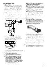
6.4 Siphon heating
(M50, M06 option 7)
When a siphon heater is present to protect the
siphon from frost, the siphon heater must be
assigned in parameter M06 to the “Siphon heating”
function. Check which relay the siphon heater is
connected to and choose option 7 for that relay.
Switching temperature (M50-06)
The siphon heater is switched on by the unit at a
preset temperature. This temperature is preset in the
unit and can be altered when desired in parameter
M50-06.
Temperature sensor (M50 option 1)
When a separate temperature sensor is present for
the siphon heater, the separate temperature sensor
must be assigned in parameter M50 to the “Siphon
temperature” function. Check which temperature
input the temperature sensor is connected to and
choose option 1 for that temperature input.
When there is no separate temperature sensor
present for the siphon heater, the relay will be
controlled by the outdoor temperature (NTC1).
6.5 Constant flow control
(M02-10option 0)
When using a switch to control the ventilation, the
unit must be set to option 0 “Constant Flow” in
M02-10. In the chapter about the air volume control
is explained how to change the air volume of each
ventilation speed.
Separate speed switches (M05)
Each connected switch must be assigned in
parameter M05 to the desired ventilation speed.
Check which digital input the switch is connected to
and choose the desired option for that digital input/
switch.
Ventilation speeds in M05
Option
Ventilation speed 1
1
Ventilation speed 2
2
Ventilation speed 3
3
Ventilation speed 4
4
When two switches are activated at the same time
the unit will run on the highest activated ventilation
speed. Regardless of the set volume of that
ventilation speed.
SAG 0-3CV (M05 and M50-03)
When a “SAG 0-3CV”switch is
present, one digital input is spared
by switching to the second
ventilation speed when two inputs
are controlled simultaneously. The
connected digital inputs must be
assigned in parameter M05 to the correct ventilation
speeds.
Assign the first connected digital input of the “SAG
0-3CV” to option 1 “Ventilation speed 1” (in the case
of the schematic displayed in the installation chapter
this is digital input 4).
Assign the second connected digital input of the
“SAG 03-CV” to option 3 “Ventilation speed 3” (in the
case of the schematic displayed in the installation
chapter this is digital input 6).
Set parameter M50-03 to “1” to indicate the presents
of a “SAG 0-3V” switch.
Ventilation speed 4 is not used by the “SAG 0-3CV”.
When a fourth ventilation speed is also desired a
separate switch must be connected and assigned as
described for the separate speed switches.
3 Position switch (Umschaltend)
When a 3 Position switch is
present, the connected digital
inputs must be assigned in
parameter M05 to the correct
ventilation speeds. Assign the first
connected digital input of the 3
Position switch to option 3 “Ventilation speed 3” or
“Enable time clock” (in the case of the schematic
displayed in the installation chapter this is digital
input 4).
Summary of Contents for ComfoAir 1500
Page 1: ...ComfoAir XL ComfoAir Eco Manual Cooling Fresh Air Clean Air Heating...
Page 45: ...EN 45...
Page 46: ...46 EN...
Page 47: ...EN 47...


