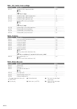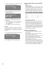
22 - EN
When an alternative response is desired, both
parameters must be set at all times. Even if
only the supply or only exhaust must respond
differently.
When the fire contact is enabled the Bypass will
automatically open in all fire response scenarios.
6.15 Dirty filter alert
(M70, M06)
The unit is equipment with two dirty filter alerts to
indicate when the filters must be replaced:
�
One for the exhaust filter (E44);
�
One for the supply filter (E45).
These dirty filter alerts are preset and can be altered
when desired in parameter M70.
Function
Parameter
Supply volume (m3/h) point 1
M70-01
Supply pressure (Pa) point 1
M70-02
Supply volume (m3/h) point 2
M70-03
Supply pressure (Pa) point 2
M70-04
Exhaust volume (m3/h) point 1
M70-05
Exhaust pressure (Pa) point 1
M70-06
Exhaust volume (m3/h) point 2
M70-07
Exhaust pressure (Pa) point 2
M70-08
Hysterese bandwith (%)
M70-09
Mesasurment Time pressure
M70-12
Maximum filter pressure
M70-13
Hysteresis (%)
Alarm off
Alarm on
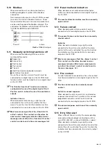
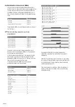
The unit will calculate the average pressure over the
time set in parameter M70-12.
When the average pressure stays below the “alarm
on” line, the dirty filter alert will stay off.
As soon as the average pressure rises above the
“alarm on” line for at least 24 hours, the dirty filter
alert will turn on.
As long as the average pressure stays above the
“alarm off” line, the dirty filter alert will not turn off
after resetting the unit.
The start and end point of the “alarm on” line is
set in parameter M70. The “alarm off” line is a
set percentage below the “alarm on” line. This
percentage (“hysteresis”) is set in parameter M70-
09.
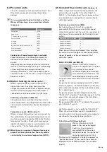
Dirty filter protection (M70-13)
When the filter is not replaced in time the filter
could tear and damage the unit. To protect the unit
against damage a maximum allowed pressure over
the filter is set in parameter M70-13. When the set
level is reached the unit will start powering down
the corresponding fan to reduce the pressure and
will display an extra error (E47/E48). When the set
maximum pressure is higher than the range of the
pressure sensors (>550Pa) the filter protection will
never turn on.
Indicator (M06 option 12)
When an indicator (e.g. a light) is present to verify
whether the dirty filter alert of the unit is activated,
the indicator must be assigned in parameter M06 to
the “Filter Alarm active” function. Check which relay
the indicator is connected to and choose option 12
for that relay/indicator.
6.16 External supply air temperature
sensor
When an external supply air temperature sensor is
present, the temperature sensor must be assigned
in parameter M50 to the “Adopt function of NTC5”
function. Check which temperature input the
temperature sensor is connected to and choose
option 2 for that digital input/switch.
6.17 Battery
(M06, M07)
Battery pump (M06)
When the battery is controlled by a pump, this
battery pump must be assigned in parameter M06
to the desired “Pump” function. Check the type of
battery controlled and to which power relay output
the battery pump is connected and choose the
desired “Pump” function for that power relay output.
Pump functions in M06
Option
Post-Heater pump
5
Post-Cooler pump
6
Post-Cooler/Heater pump
9
PreHeater ODA (= supply) pump
11
PreHeater ETA (= extract) pump
13
Battery valve (M07)
When the battery is controlled by a valve, this
battery valve must be assigned in parameter M07
to the desired “Valve” function. Check the type of
battery controlled and to which analog output the
battery valve is connected and choose the desired
“Valve” function for that analog output.
Valve functions M07
Option
Post-Heater valve
4
Post-Cooler valve
5
Post-Cooler/Heater valve
6
PreHeater ODA (= supply) valve 8
PreHeater ETA (= extract) valve
9
Summary of Contents for ComfoAir 1500
Page 1: ...ComfoAir XL ComfoAir Eco Manual Cooling Fresh Air Clean Air Heating...
Page 45: ...EN 45...
Page 46: ...46 EN...
Page 47: ...EN 47...

