12 - EN
EN - 13
5.3 Condensation drain
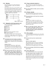
Plate exchanger
The plate exchanger is placed in a drip tray which
is fitted with a membrane siphon as standard. The
membrane siphon connects to a plastic 32mm drain
through which condensation can be drained directly.
The condensation drain must have a free outlet to
the siphon of the domestic waste-water system.
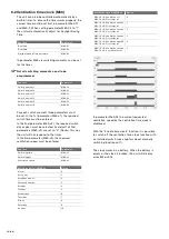
Cooling battery
Each cooling battery is placed in a drip tray fitted
with a 32mm plastic drain. In order to prevent
external air leakage, a membrane siphon must be
connected to this plastic drain on site.
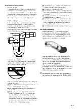
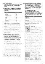
Use a siphon with water lock if the cooler is installed
behind the fan (overpressure).
Use a membrane siphon if the cooler is installed
in front of the fan (underpressure). The membrane
siphon does not lock the output pipe with a water
lock, but with a self-locking valve.
135?
Take account of the following factors when fitting the
condensation drain:
�
Spray or blow the membrane siphon before first
use to loosen the non-return valve;
�
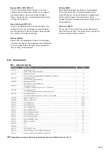
The membrane siphon must be mounted at an
angle of 45°;
�
When determining the height of the water lock
(siphon with water lock), take into account not
only the total pressure in the casing, but also
pressure surges that may occur when the valves
are opened and closed, for example. The supplied
overpressure siphon is suitable for overpressures
of up to 600Pa in the cooling section;
�
The siphon with water lock must be fitted with a
sealable filler opening and drain option;
�
One siphon is fitted for each drain;
�
The siphon with water lock must first be filled with
water when (re)starting the unit after a long period
of inactivity;
�
The siphon must be connected air-tight to the
condensation drain of the unit;
�
The siphon may not be connected directly to the
domestic waste-water system. The siphon must
have a free outlet to the siphon of the domestic
waste-water system;
�
The condensation must be drained off frost-free.
5.4 Siphon heating
Siphons are sensitive to frost. A siphon heater
reduces the risk of frost damage. A siphon heater
is a heating spiral that can be wrapped around the
siphon. In order to maximize heating efficiency, the
heating spiral is insulated on the outside.
A present siphon heater must be connected to his
own relay output on the I/O PCB. The connected
relay can be controlled by the standard temperature
sensor T1 of the unit or by a separate temperature
sensor installed near the siphon.
When using a separate temperature sensor the
temperature sensor must be connected to one of the
spare temperature inputs (NTC6 located on the main
PCB or NTC7 located on the I/O PCB)
The separate temperature sensor of the siphon
heating can only be connected to NTC6 or NTC7.
Summary of Contents for ComfoAir 1500
Page 1: ...ComfoAir XL ComfoAir Eco Manual Cooling Fresh Air Clean Air Heating...
Page 45: ...EN 45...
Page 46: ...46 EN...
Page 47: ...EN 47...


