


11
English
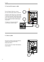
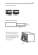
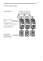
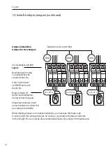
5. Electrical connection
PE
N
L1 L2 L3
PE
N
L1 L2 L3
PE
L1 L2 L3
PE
L1 L2
Max
6 mm
2
Max 12 mm
Click!
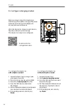
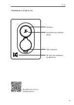
If you are installing the charger on an IT
grid, please check zendesk.zaptec.com
Connect all wires and firmly press down
all levers as illustrated. When the wires are
safely attached, replace the terminal cover
and turn on the circuit breaker.
Ferrules are optional.
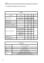
Electrical wire dimensions
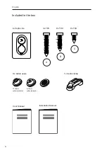
Summary of Contents for Go
Page 1: ...Zaptec Smart small and safe Zaptec Go Installation Manual...
Page 2: ......
Page 3: ......
Page 204: ...168 Zaptec Charger AS Zaptec Type 2 zaptec com guarantee Zaptec...
Page 205: ...169 Zaptec Go Zaptec Type 2 RFID QR...
Page 206: ...170 1 x Zaptec Go 4 x T20 2 x T20 2 x T20 A B C 3 x 1x 12 18 8 14...
Page 207: ...171 1 C 2 A 0 9 0 9...
Page 208: ...172 3 1 2 3 Zaptec Go RCD A 1 2 3 4 B 3 Nm...
Page 212: ...176 7 9 8 C 1 Nm Zaptec Go Zaptec App Zaptec Go...
Page 213: ...177 40A 40A 40A RCD Type A Zaptec Go RCD Type A Zaptec Go RDC DD 6mA DC IEC 62955 1 10 32 NB...
Page 215: ...179 11 Eco Zaptec App RFID...
Page 216: ...180 12 Zaptec zaptec com support...
Page 218: ...182 14...


