c.6 Starting the stove
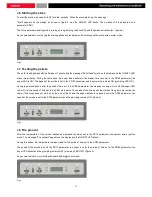
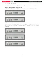
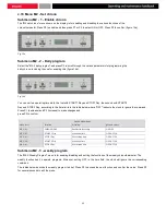
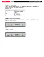
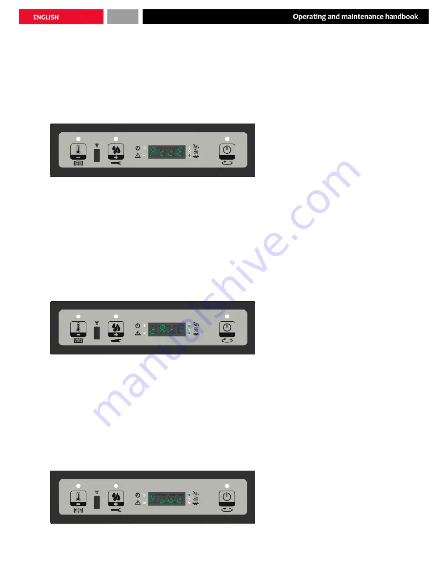
To start the stove, press and hold P3 for a few seconds. When the stove starts up, the message
"Start" appears on the display, as shown in figure 4, and the ON/OFF LED blinks. The duration of this phase is set in
parameter PRO1.
The stove enters pre-heating mode, turning on the glow plug (and its LED) and the smoke extraction fan. (figure 4)
Any anomalies that occur during the start-up phase are indicated on the display and the stove enters alarm mode.
Fig.4
c.7 Feeding the pellets
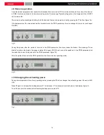
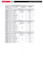
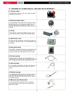
The pellet feeding phase starts after about 1 minute and the message "Pellet feed" scrolls on the display and the ON/OFF LED
blinks intermittently. During the first phase, the auger feeds pellets to the brazier for a time set in the PR40 parameter (the
auger LED is ON). The speed of the smoke is set in the PR 42 parameter and the glow plug remains ON (glow plug LED ON).
During the second phase, after the period of time set in the PR40 parameter has elapsed, the auger turns off (the auger LED
turns off) for the period of time set in the PR41 parameter. The speed of the smoke and the status of the glow plug remain the
same. If the stove does not start up by the end of this phase, the auger restarts for a period set in the PR04 parameter, the
speed of the smoke is set in the PR16 parameter and the glow plug remains ON. (figure 5)
Fig.5
c.8 Fire present
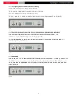
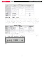
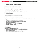
After the temperature of the smoke reaches and exceeds the value set in the PR13 parameter, the system enters ignition
mode. The message "Fire present" appears on the display and the ON/OFF LED blinks.
During this phase, the temperature remains stable for the period of time set in the PR02 parameter.
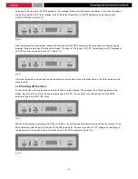
The speed of the smoke is set in the PR17 parameter, the auger runs for the period of time set in the PR05 parameter (the
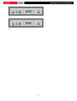
auger LED blinks) and the glow plug remains OFF (glow plug LED OFF). (figure 6)
Any anomalies that occur will stop the board and trigger error mode.
Fig.6
15
Summary of Contents for HEBE
Page 1: ...PELLET STOVE HEBE OPERATING AND MAINTENANCE HANDBOOK...
Page 2: ......
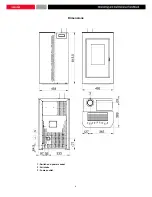
Page 8: ...Dimensions 1 Switch and power socket 2 Air intake 3 Fumes outlet 8...
Page 22: ...Fig 13f Fig 13 22...
Page 34: ...34...
Page 35: ...35...

