


835966-UIM-E-0814
Johnson Controls Unitary Products
21
SECTION VIII: SYSTEM START-UP
ENERGIZE CRANKCASE HEATER
In order to energize the crankcase heater, set the indoor cooling ther-
mostat to the OFF position. Close the line power disconnect to the unit.
WITH POWER TO UNIT AND THERMOSTAT IN COOLING
POSITION:
1. In the cooling cycle, discharge gas is pumped to the outdoor coil
which is the condenser. The indoor coil is the evaporator.
2. If fan switch is in ON position, a circuit is made through blower relay
to provide continuous blower operation.
3. With fan switch in AUTO position, a circuit is made from thermostat
cooling contact through blower relay to provide blower operation.
4. System will cycle with thermostat demand to provide cooling as
needed.
SECTION IX: SYSTEM OPERATION
For more information on the control operation, refer to the “OPERA-
TION INSTRUCTIONS - DEMAND DEFROST CONTROL BOARD”
publication.
REQUIRED CONTROL SETUP
1. Consult system wiring diagram to determine proper thermostat wir-
ing for your system.
2. If hot heat pump configuration is desired, change HOT HEAT PUMP
jumper to ON position. This setting MUST be set on the defrost
board.
3. If installation includes a fossil fuel furnace, change FUEL jumper to
ON position. This setting MUST be set on the defrost board.
4. Set low temperature cutout (LTCO), balance point (BP), switch point
(SP), and Y2 Lock jumpers as desired. These settings may be mod-
ified by communicating thermostat.
5. Verify proper system functionality. Confirm room thermostat opera-
tion including fault code display capability.
6. Upon completion of installation, verify that no fault codes are stored
in memory. Clear the fault code memory if necessary.
DEFROST OPERATION
The following defrost curve selection jumper positions are set from fac-
tory.
NOTE:
For information on the 5 & 6 pins, refer to the “Operation Instructions -
Demand Defrost Control Board” publication.
An attempt to start the compressor without at least 8 hours of crank-
case heat will damage the compressor.
The following steps must be taken at the time of installation to insure
proper system operation.
TABLE 3:
Defrost Initiate Curves
Defrost Curve Selection
Jumper Position
PIN 1
PIN 2
PIN 3
PIN 4
16 SEER
Heat Pump Model
2-Ton
2.5-Ton
3-Ton
3.5-Ton
5-Ton
4-Ton
–
–
18 SEER
Heat Pump Model
2-Ton
4-Ton
5-Ton
3-Ton
–
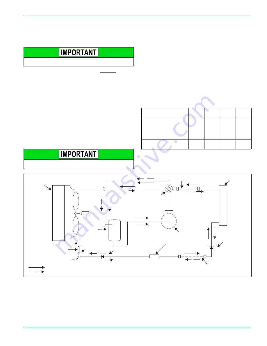
FIGURE 21:
Heat Pump Flow Diagram
.
FLOW RATER
(Cooling)
COOLING CYCLE FLOW
HEATING CYCLE FLOW
INDOOR COIL
4-WAY
REVERSING
VALVE
SUCTION
ACCUMULATOR
COMPRESSOR
OUTDOOR
COIL
FIELD CONNECTED LINE
FILTER DRYER
(Solid core)
LIQUID
SENSOR
FIELD CONNECTED LINE
FLOW RATER
(Heating)
A019-001