background image

JOHNSON CONTROLS

159

SECTION 8 – TROUBLESHOOTING

FORM 155.30-ICOM2.EN.UL

ISSUE DATE: 12/21/2018

8

TROUBLESHOOTING PERFORMANCE 

ISSUES

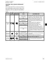
TABLE 44 - 

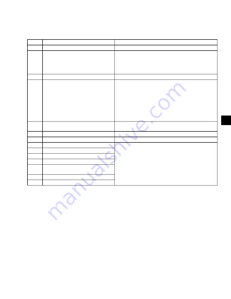
TROUBLESHOOTING PERFORMANCE 

ISSUES

ITEM

CAUSE

COUNTERMEASURE

1

Cooling water temperature is high.

Check the capacity of the cooling tower.

2

Cooling water is insufficient.

• See if the cooling water supply rate matches the specification. 

• 


Check the flow meter, discharge pressure of the cooling water 

pump, current, and so on.

• 


If the flow rate is insufficient, check the opening ratio of the flow 

controller valve and check the strainer for clogging.

3

Cooling water heat exchange tube is dirty.

Contact your local Johnson Controls Service Office.

4

Non-condensable gas remains in machine.

• See 

Purge Procedure on page 130

• Check the capacity of the vacuum pump. 
• Check the purge unit for trouble. 
• 


Purge air from the absorption chiller. If partial-load operation is 
continued for a long period, non-condensable gas tends to stay 
in the absorber. In this case, purge directly from the low-pressure 
side (absorber). See 

Purge Procedure on page 130

. Even if the 

automatic purge unit is installed, purge from the lower pressure 
side (absorber) manually.

5

Chilled water outlet temperature controller is 

not set properly.

Check that the chilled water outlet temperature controller on the 
control panel by the machine is set to the target value.

6

Manual refrigerant blow valves are kept open. Check that manual refrigerant blow valve V8 is closed.

7

Refrigerant pump 

Stop

 button is pressed.

Press the Refrigerant Pump 

Auto

 button.

8

Corrosion inhibitor is depleted.

Contact your local Johnson Controls Service Office.

9

Surface active agent is depleted.

10

Refrigerant is dirty (contains solution).

11

Internal cycle control valve is not set properly.

12

Chilled water outlet temperature controller is 

broken.

13

Solution is crystallized.

14

Air leaks in absorption chiller.

If the performance is insufficient while the hot water 

control valve is fully opened or if the hot water control 

valve does not fully open while the load is sufficient, 

check numbers 1-7 in the above table in order. If the 

cause of the trouble is other than numbers 1-7, it may 

be one of number 8-14. In this case, contact your local 

Johnson Controls Service Center immediately.

Summary of Contents for YHAU-CL Series

Page 1: ...NGLE EFFECT HOT WATER ABSORPTION CHILLER INSTALLATION OPERATION MAINTENANCE NEW RELEASE Form 155 30 ICOM2 EN UL 1218 Issue Date December 21 2018 LD22981 LD22981 Model YHAU CL CH 30 2000 TON 105 7043 k...

Page 2: ...t and any referenced materials This in dividual shall also be familiar with and comply with all applicable industry and governmental standards and regulations pertaining to the task in question SAFETY...

Page 3: ...e man ual or product owner It is the responsibility of rigging lifting and operating service personnel to verify the applicability of these documents to the equipment If there is any question regardin...

Page 4: ...CAPACITY HEAT SOURCE L Low Temp hot water H High Temp hot water UNIT York Absorption Chiller DESIGN SYMBOL MODEL SERIES NAME EXE 30 500 RT nominal capacity EXW2S 630 1000 RT nomi nal capacity EXW4S 1...

Page 5: ...e Machine on Rollers 23 Jacking the machine 25 Structural Support and Installation 27 Indoor and Outdoor Installation 27 Electrical 27 Precautions for Use 27 Leak testing 28 Electrical Shock Cautions...

Page 6: ...7 MAINTENANCE 129 Valve Inspection 129 Solenoid Valves 129 Pump Shut Off Valves 129 Air Purge Valves And Drain Valves For Chilled Water Cooling Water And Hot Water 129 Purge Valves 129 Start the Chil...

Page 7: ...ppage of the Absorption Chiller 143 Chemical Treatment 143 Flow Speed in Tubes 144 Storage Method of the Chiller 144 Wet Storage Method 144 Dry Storage Method 145 Precautions Against External Damage 1...

Page 8: ...66 FIGURE 27 PLC Output Wiring 68 FIGURE 28 Display Analog Input Wiring 70 FIGURE 29 Display Analog Input Wiring 72 FIGURE 30 Display Analog Output Wiring 74 FIGURE 31 PLC and Display Wiring 75 FIGURE...

Page 9: ...r EXE Series Chiller 133 FIGURE 60 Purge Unit 134 FIGURE 61 Chilled Water and Cooling Water System 149 FIGURE 62 Hot Water System 150 FIGURE 63 Duhring Diagram PTX Chart F 151 FIGURE 64 Duhring Diagra...

Page 10: ...Communication Specification Modbus RTU 87 TABLE 23 Rotary Pump Rotation 89 TABLE 24 Liquid Level Gauges 90 TABLE 25 Failure List 121 TABLE 26 Alarm List 122 TABLE 27 Safety Switches 127 TABLE 28 Solen...

Page 11: ...ntenance resulting from a failure to follow the procedures and instructions detailed in this manual WARRANTY Johnson Controls warrants YHAU CL CH chillers in accordance with the Limited Warranty Engin...

Page 12: ...ntenance on live equipment must not be at tempted No attempt should be made to gain access to the control panel or electrical enclosures during normal operation of the unit Components may also have sh...

Page 13: ...arning Risk of electric shock General attention symbol Warning On isolating the supply it may take up to 300 seconds for the capacitor voltage to fall below 50 volts Warning Risk of fire Warning Risk...

Page 14: ...JOHNSON CONTROLS 14 FORM 155 30 ICOM2 EN UL ISSUE DATE 12 21 2018 THIS PAGE INTENTIONALLY LEFT BLANK...

Page 15: ...sable gas from the machine SECTION 2 PRODUCT DESCRIPTION CONTROL PANEL The absorption chiller comes with a factory mounted and pre wired control system The control panel en closure is equipped with a...

Page 16: ...erant The vapor pressure of the LiBr solution is directly related to the amount of refrigerant water present in the solu tion with the LiBr and the solution temperature Figure 2 SINGLE EFFECT HOT WATE...

Page 17: ...e and temperature The solution flows into the top of the lower absorber section When the LiBr solution enters the lower Ab sorber section it is already diluted by the refrigerant vapor that boiled off...

Page 18: ...d refrigerant in the condenser section using cooling condenser water The liquid refrigerant water is then distributed first in the lower evaporator section LD19939a4 LD19839a4 Condenser Cooling Water...

Page 19: ...weight Although the crystallization line on Figure 64 on page 152 does not extend that far you can see that the solution at 45 concentration will not have a tendency to crystallize at normal ambient...

Page 20: ...JOHNSON CONTROLS 20 FORM 155 30 ICOM2 EN UL ISSUE DATE 12 21 2018 THIS PAGE INTENTIONALLY LEFT BLANK...

Page 21: ...plant room will ever drop below 50 F you must have the cold ambient option for outdoor installation LD18119 DANGER Rigging and lifting should only be done by a professional rigger in accordance with...

Page 22: ...n cause serious damage and are costly repairs Therefore use diligence in keeping the machine body free from moisture at all times 2 Problems and Preventative Measures PROBLEM PREVENTATIVE MEASURE Free...

Page 23: ...load This is can cause damage to the machine and pose a risk to the machine installer or persons moving the unit MOVING THE MACHINE ON ROLLERS Plan the entrance for the machine from Figure 4 below Do...

Page 24: ...924_UL Maximum Machine Width Maximum Machine Length Maximum Machine Height Skid Base Approx Approx Appr ox 3 93 3 93 3 93 7 86 7 86 15 72 Figure 4 MOVING THE MACHINE ON ROLLERS LD22923 TIR ROLLER SET...

Page 25: ...ORM 155 30 ICOM2 EN UL ISSUE DATE 12 21 2018 3 JACKING THE MACHINE When jacking up the machine be sure to fit a jack in each of the jack up supports as Shown in Figure 7 be low LD22926 JACK UP SUPPORT...

Page 26: ...E INSTALLATION AND REASSEMBLY Operate the front and rear jacks alternately Do not jack up the machine more than about 0 78 inch at a time Each time the machine is jacked up adhere it with a suitable c...

Page 27: ...according terminals securely Loose fitting cables can cause the terminals to heat up resulting in fire or elec trical shock CAUTION The chiller does NOT arrive with a ground fault earth leakage cir cu...

Page 28: ...el this can cause electric shock Do not touch any part other than the control panel of the machine and the valves described in the operating manual this can cause a malfunction and injury Apply only t...

Page 29: ...rubber vibration isolators to the unit base as shown in Figure 9 on page 31 Use liners to adjust the levelness of the unit For unit dimensions see Table 8 on page 40 ITEM DESCRIPTION 1 Nut 2 Washer 3...

Page 30: ...piping material to be compatible with the refrigerant in the system The refrigerant is de ionized water that could exceed 200 F 93 3 C in some cases Johnson Con trols recommends using schedule 40 ste...

Page 31: ...TORAGE INSTALLATION AND REASSEMBLY FORM 155 30 ICOM2 EN UL ISSUE DATE 12 21 2018 3 LD28267 Purge Tank Rupture Disk Solution Heat Exchanger Generator Control Panel Evaporator Absorber Condenser Rupture...

Page 32: ...6 8 53 2 6 5 25 1 6 3 28 1 1 764 0 8 130EXE 10 17 3 1 5 91 1 8 6 89 2 1 11 464 5 2 13 889 6 3 10 17 3 1 5 25 1 6 3 28 1 2 205 1 160EXE 12 14 3 7 5 91 1 8 6 89 2 1 13 889 6 3 16 314 7 4 11 81 3 6 5 25...

Page 33: ...2 6 5 25 1 6 3 28 1 1 764 0 8 130EXE 10 17 3 1 5 91 1 8 6 89 2 1 11 464 5 2 13 889 6 3 10 17 3 1 5 25 1 6 3 28 1 2 205 1 160EXE 12 14 3 7 5 91 1 8 6 89 2 1 13 889 6 3 16 314 7 4 11 81 3 6 5 25 1 6 3 2...

Page 34: ...hese images are representations of nozzle arrangements Reference general arrangement drawings for detailed nozzle locations for each specific unit ITEM DESCRIPTION 1 Chilled Water Outlet Odd Pass 2 Co...

Page 35: ...e images are representations of nozzle arrangements Reference general arrangement drawings for detailed nozzle locations for each specific unit 1 2 3 4 5 6 7 8 9 B SIDE A SIDE LD19910b ITEM DESCRIPTIO...

Page 36: ...le 5 on page 36 2 Use a bonding agent iron wire iron band or other aproved bonding agents to fix the hot insulation cold insulation material Never rivet them The use of welding pins is not permitted T...

Page 37: ...N 3 HANDLING STORAGE INSTALLATION AND REASSEMBLY FORM 155 30 ICOM2 EN UL ISSUE DATE 12 21 2018 3 LD20596 Hot Insulation Cold Insulation Figure 14 HOT COLD INSULATION EXE MODELS LD20595 Figure 15 HOT C...

Page 38: ...EN UL ISSUE DATE 12 21 2018 SECTION 3 HANDLING STORAGE INSTALLATION AND REASSEMBLY Figure 17 INTERIOR OF CONTROL PANEL Figure 16 EXTERIOR OF CONTROL PANEL LD28253 LD28266 Ground Terminal Door Stopper...

Page 39: ...are possible Please check with your Johnson Controls Service Center to see if your temperature dif ferential is possible Table 7 TYPICAL OPERATIONAL RANGE PARAMETER ALLOWABLE RANGES EUROPE FOR OTHER...

Page 40: ...7 3 29 762 13 5 39 463 17 9 65 477 29 7 500EXE 29 762 13 5 41 006 18 6 73 193 33 2 35 053 15 9 46 297 21 78 485 35 6 630EXW2S 35 935 16 3 50 265 22 8 86 421 39 2 41 667 18 9 55 997 25 4 92 153 41 8 70...

Page 41: ...E 12 8 3 9 13 29 4 05 7 71 2 35 10 5 3 2 10 5 3 2 400EXE 15 42 4 7 15 91 4 85 7 71 2 35 10 5 3 2 13 12 4 500EXE 18 7 5 7 19 19 5 85 7 71 2 35 10 5 3 2 16 4 5 630EXW2S 18 04 5 5 18 04 5 5 9 02 2 75 10...

Page 42: ...08 0 88 21 9 0 62 320EXE 150 69 14 204 51 19 3 1 39 13 77 0 39 36 02 1 02 26 13 0 74 400EXE 182 99 17 236 81 22 3 9 48 7 16 6 0 47 42 02 1 19 31 43 0 89 500EXE 215 28 20 301 39 28 4 9 60 9 19 42 0 55...

Page 43: ...ISSUE DATE 12 21 2018 4 LOAD POINTS FOR EXE AND EXW UNITS CL MODELS LD22036 Load Point 1 Load Point 2 Load Point 4 Load Point 3 Load Point 4 Load Point 3 Load Point 1 Load Point 2 LD22036a Figure 18...

Page 44: ...33 7 341 3 33 7 341 3 33 7 341 3 33 400EXE 9 502 4 31 9 502 4 31 7 584 3 44 7 584 3 44 500EXE 11 596 5 26 11 596 5 26 8 907 4 04 8 907 4 04 630EXW2S 14 352 6 51 10 781 4 89 14 352 6 51 10 781 4 89 70...

Page 45: ...EN UL ISSUE DATE 12 21 2018 4 LOAD POINTS FOR EXE AND EXW UNITS CH MODELS LD22997A Load Point 1 Load Point 2 Load Point 4 Load Point 3 Figure 20 YHAU CH30EXE 500EXE LD22997B Load Point 1 Load Point 2...

Page 46: ...3 93 8 664 3 93 8 664 3 93 400EXE 10 957 4 97 10 957 4 97 8 774 3 98 8 774 3 98 500EXE 13 073 5 93 13 073 5 93 10 075 4 57 10 075 4 57 630EXW2S 16 006 7 26 11 993 5 44 16 006 7 26 11 993 5 44 700EXW2S...

Page 47: ...JOHNSON CONTROLS 47 SECTION 4 TECHNICAL DATA 4 THIS PAGE INTENTIONALLY LEFT BLANK...

Page 48: ...12 3 AC460V 3Ph 60Hz 3 0 12 9 3 0 12 9 50EXE AC200V 3Ph 50Hz 32A 160A 1 1 6 9 25 2 1 1 6 9 25 2 AC200V 3Ph 60Hz 6 2 22 2 6 2 22 2 AC220V 3Ph 60Hz 6 1 24 6 6 1 24 6 AC380V 3Ph 50Hz 20A 160A 3 4 12 1 3...

Page 49: ...0 3 4 1 6 9 0 6 4 5 1 1 03 3 8 1 6 9 0 7 0 5 6 18 1 05 4 0 1 6 9 0 7 2 5 8 50EXE 0 2 2 4 7 0 0 75 3 8 20 6 7 2 5 8 50 2 0 6 8 3 4 20 6 6 5 5 2 2 06 7 6 3 4 20 6 7 0 5 6 1 1 3 0 1 8 9 0 6 7 5 3 36 1 0...

Page 50: ...0 12 9 160EXE AC200V 3Ph 50Hz 50A 160A 2 2 11 6 48 0 1 1 6 9 25 2 AC200V 3Ph 60Hz 11 4 40 6 6 2 22 2 AC220V 3Ph 60Hz 10 6 44 8 6 1 24 6 AC380V 3Ph 50Hz 32A 160A 6 1 23 0 3 4 12 1 AC380V 3Ph 60Hz 6 2 1...

Page 51: ...7 6 9 18 1 05 4 0 1 6 9 0 8 9 7 2 160EXE 0 2 2 4 7 0 0 75 3 8 20 6 8 9 7 1 50 2 0 6 8 3 4 20 6 8 3 6 6 2 06 7 6 3 4 20 6 8 7 7 0 1 1 3 0 1 8 9 0 8 5 6 8 36 1 0 2 5 1 8 9 0 8 3 6 7 1 12 3 3 1 8 9 0 8...

Page 52: ...0EXE AC200V 3Ph 50Hz 50A 160A 3 0 15 6 60 0 2 2 11 6 48 0 AC200V 3Ph 60Hz 14 8 53 2 11 4 40 6 AC220V 3Ph 60Hz 14 4 59 0 10 6 44 8 AC380V 3Ph 50Hz 32A 160A 8 1 29 0 6 1 23 0 AC380V 3Ph 60Hz 8 2 23 0 6...

Page 53: ...8 1 5 4 7 1 6 9 0 12 6 10 1 500EXE 0 4 3 3 8 8 0 75 3 8 20 6 12 2 9 7 50 2 8 8 2 3 4 20 6 11 5 9 2 2 9 9 0 3 4 20 6 12 2 9 8 1 6 4 2 1 8 9 0 11 9 9 5 36 1 4 3 9 1 8 9 0 11 9 9 5 1 65 4 4 1 8 9 0 12 1...

Page 54: ...000EXW2S AC200V 3Ph 50Hz 63A 160A 5 5 26 0 132 0 2 2 12 4 42 0 AC200V 3Ph 60Hz 25 0 118 0 11 6 46 0 AC220V 3Ph 60Hz 22 8 130 0 11 0 48 0 AC380V 3Ph 50Hz 40A 160A 14 2 60 0 6 5 20 3 AC380V 3Ph 60Hz 14...

Page 55: ...3 4 14 0 1 6 9 0 17 4 13 9 1000EXW2S 1 3 7 6 25 6 0 75 3 8 20 6 17 6 14 0 50 7 2 25 0 3 4 20 6 16 7 13 3 7 0 26 0 3 4 20 6 17 1 13 7 3 9 11 9 1 8 9 0 17 7 14 1 36 3 7 10 7 1 8 9 0 17 3 13 8 3 8 12 8...

Page 56: ...30 0 AC400V 3Ph 50Hz 19 2 72 0 10 1 36 0 AC415V 3Ph 50Hz 18 6 73 5 9 8 37 0 AC400V 3Ph 60Hz 18 0 67 0 9 5 35 0 AC440V 3Ph 60Hz 17 0 73 0 9 0 37 0 AC460V 3Ph 60Hz 16 5 76 0 8 8 38 0 1800EXW4S AC200V 3P...

Page 57: ...19 7 36 4 9 9 0 1 8 9 0 24 2 19 4 4 5 13 0 1 8 9 0 25 0 20 0 4 4 13 5 1 8 9 0 25 2 20 1 4 2 12 0 1 6 9 0 23 4 18 7 4 0 13 2 1 6 9 0 24 4 19 5 18 3 9 13 8 1 6 9 0 24 8 19 9 1800EXW4S 2 2 12 4 42 0 0 7...

Page 58: ...JOHNSON CONTROLS 58 FORM 155 30 ICOM2 EN UL ISSUE DATE 12 21 2018 SECTION 4 TECHNICAL DATA Figure 22 POWER WIRING Electrical Diagram for UL...

Page 59: ...JOHNSON CONTROLS 59 SECTION 4 TECHNICAL DATA FORM 155 30 ICOM2 EN UL ISSUE DATE 12 21 2018 4 FIGURE 22 POWER WIRING CONT D LD28190_UL...

Page 60: ...JOHNSON CONTROLS 60 FORM 155 30 ICOM2 EN UL ISSUE DATE 12 21 2018 SECTION 4 TECHNICAL DATA Figure 23 POWER WIRING Electrical Diagram for UL...

Page 61: ...JOHNSON CONTROLS 61 SECTION 4 TECHNICAL DATA FORM 155 30 ICOM2 EN UL ISSUE DATE 12 21 2018 4 FIGURE 23 POWER WIRING CONT D LD28191_UL...

Page 62: ...JOHNSON CONTROLS 62 FORM 155 30 ICOM2 EN UL ISSUE DATE 12 21 2018 SECTION 4 TECHNICAL DATA Figure 24 PLC INPUT WIRING Electrical Diagram for UL...

Page 63: ...JOHNSON CONTROLS 63 SECTION 4 TECHNICAL DATA FORM 155 30 ICOM2 EN UL ISSUE DATE 12 21 2018 4 FIGURE 24 PLC INPUT WIRING CONT D LD28192_UL...

Page 64: ...JOHNSON CONTROLS 64 FORM 155 30 ICOM2 EN UL ISSUE DATE 12 21 2018 SECTION 4 TECHNICAL DATA Figure 25 PLC INPUT WIRING Electrical Diagram for UL...

Page 65: ...JOHNSON CONTROLS 65 SECTION 4 TECHNICAL DATA FORM 155 30 ICOM2 EN UL ISSUE DATE 12 21 2018 4 LD28193_UL FIGURE 25 PLC INPUT WIRING CONT D...

Page 66: ...JOHNSON CONTROLS 66 FORM 155 30 ICOM2 EN UL ISSUE DATE 12 21 2018 SECTION 4 TECHNICAL DATA Figure 26 PLC OUTPUT WIRING Electrical Diagram for UL...

Page 67: ...JOHNSON CONTROLS 67 SECTION 4 TECHNICAL DATA FORM 155 30 ICOM2 EN UL ISSUE DATE 12 21 2018 4 LD28195_UL FIGURE 26 PLC OUTPUT WIRING CONT D...

Page 68: ...JOHNSON CONTROLS 68 FORM 155 30 ICOM2 EN UL ISSUE DATE 12 21 2018 SECTION 4 TECHNICAL DATA Figure 27 PLC OUTPUT WIRING Electrical Diagram for UL...

Page 69: ...JOHNSON CONTROLS 69 SECTION 4 TECHNICAL DATA FORM 155 30 ICOM2 EN UL ISSUE DATE 12 21 2018 4 LD28196_UL FIGURE 27 PLC OUTPUT WIRING CONT D...

Page 70: ...JOHNSON CONTROLS 70 FORM 155 30 ICOM2 EN UL ISSUE DATE 12 21 2018 SECTION 4 TECHNICAL DATA Figure 28 DISPLAY ANALOG INPUT WIRING Electrical Diagram for UL...

Page 71: ...JOHNSON CONTROLS 71 SECTION 4 TECHNICAL DATA FORM 155 30 ICOM2 EN UL ISSUE DATE 12 21 2018 4 LD28197_UL FIGURE 28 DISPLAY ANALOG WIRING CONT D...

Page 72: ...JOHNSON CONTROLS 72 FORM 155 30 ICOM2 EN UL ISSUE DATE 12 21 2018 SECTION 4 TECHNICAL DATA Figure 29 DISPLAY ANALOG INPUT WIRING Electrical Diagram for UL...

Page 73: ...JOHNSON CONTROLS 73 SECTION 4 TECHNICAL DATA FORM 155 30 ICOM2 EN UL ISSUE DATE 12 21 2018 4 LD28198_UL FIGURE 29 DISPLAY ANALOG INPUT WIRING CONT D...

Page 74: ...JOHNSON CONTROLS 74 FORM 155 30 ICOM2 EN UL ISSUE DATE 12 21 2018 SECTION 4 TECHNICAL DATA LD28199_UL Figure 30 DISPLAY ANALOG OUTPUT WIRING Electrical Diagram for UL...

Page 75: ...JOHNSON CONTROLS 75 SECTION 4 TECHNICAL DATA FORM 155 30 ICOM2 EN UL ISSUE DATE 12 21 2018 4 LD28201_UL Figure 31 PLC AND DISPLAY WIRING Electrical Diagram for UL...

Page 76: ...JOHNSON CONTROLS 76 FORM 155 30 ICOM2 EN UL ISSUE DATE 12 21 2018 SECTION 4 TECHNICAL DATA Figure 32 PLC INPUT WIRING Electrical Diagram for UL...

Page 77: ...JOHNSON CONTROLS 77 SECTION 4 TECHNICAL DATA FORM 155 30 ICOM2 EN UL ISSUE DATE 12 21 2018 4 LD28200_UL FIGURE 32 PLC INPUT WIRING CONT D...

Page 78: ...JOHNSON CONTROLS 78 FORM 155 30 ICOM2 EN UL ISSUE DATE 12 21 2018 SECTION 4 TECHNICAL DATA LD20543a Figure 33 EXTERNAL CONNECTION TERMINAL DETAILS...

Page 79: ...1 Supply power source to absorption chiller is de signed as 3 phase 3 wire as a standard 2 See Table 14 on page 80 for information on the breaker capacity 3 Connect to an absorption chiller interlock...

Page 80: ...oad Analog Signal Allowed Resistance Load 550 Ohm External Absorption Chiller Control Panel Digital Signal Rating Voltage Current DC24 V 7 m A LD20545 STARTING PANEL FOR CHILLED WATER STARTING PANEL F...

Page 81: ...es and the EXW series of hot water absorp tion chillers Upper Communication System Configuration The configuration of the upper communication system is shown in Figure 38 on page 85 LD20594 Central Mo...

Page 82: ...included Wiring work for Ethernet connection X Apply twisted pair cable Communication program for central monitoring unit X Refer to this section for the details of the IP address function code commu...

Page 83: ...ndition 0 or 1 01003 0 STOP 1 OPERATION 7 Refrigerant pump condition 0 or 1 01005 0 STOP 1 OPERATION 8 Load limit condition 0 or 1 01009 0 NORMALLY OPERATION 1 LOAD LIMIT OPERATION 9 Control manipulat...

Page 84: ...must be performed by the customer to be sure that the communication systems work properly Table 20 SCOPE OF DELIVERY OF UPPER COMMUNICATION SYSTEM ITEM CUSTOMER JCI REMARKS Control panel with upper c...

Page 85: ...connection These use a GP4000 series COM2 LD20599 RDA RDB SDA SDB SG 100 1 2W 2 3 7 5 4 SG 1 Pin RDB SDA SDB RDA 9 6 CSA ERB CSB ERA 8 100 1 2W Display Shield Slave D sub 9 pin socket Signal name Ext...

Page 86: ...ce Master Your own cable Pin Signal name Termination resistance Termination resistance Shell FG LD20947 2 3 7 5 4 SG 1 RDB SDA SDB RDA 9 6 CSA ERB CSB ERA 8 100 1 2W SDA SDB RDA RDB SG 100 1 2W FG 2 3...

Page 87: ...nication path type RS422 RS485 Data Length 8 Bit Stop Bit 1 Bit Parity EVEN Speed 9600 bps Connector D Sub 9pin Function Code Read Coil Status 01 Read Holding Register 03 Device Digital Signal Coil An...

Page 88: ...A Hearing protection must be worn at all times when op erating the chiller This hearing protection may impact the manner in which operators must communicate to be understood Figure 42 SAMPLE SOUND TES...

Page 89: ...ble 23 on page 89 to see if your pump rotation is in the right direction The correct direction shows a higher discharge pressure Table 23 ROTARY PUMP ROTATION CORRECTION ROTATION Solution Circulation...

Page 90: ...not the water flow can become turbulent at the shut off valves and damage the wa ter chamber case and tubes When you need to reduce the quantity of the chilled water cooling water and hot water tempor...

Page 91: ...erant pump start The hot water control valve opens STOP THE CHILLER 1 Press the STOP button on the Control Panel To stop the chiller from a remote location enter the remote stop signal When the chille...

Page 92: ...Defective Signal Output Remote Local No 3 minutes Yes Time up Temperature Control running Yes Stop Operation Dilution Time count Hot Water Control Valve close Dilution time increasing Chilled Water R...

Page 93: ...t pipe entering the chiller and interlock these isolation valves with the chiller control panel It is important for safe and reliable operation of the chiller as well as to prevent potential crystalli...

Page 94: ...n 5 Unit is located in accordance with minimum clear ance dimensions Required maintenance space is available around the machine 6 Foundation bolts are properly installed 7 The levelness of the unit is...

Page 95: ...e quirement D Electrical 1 Main and control power supply is available 2 The insulation resistance of each motor and the MCB secondary side is within acceptable range 3 The power supply voltage is set...

Page 96: ...anel Checks 1 The thermal relays conform to the factory inspec tion sheet 2 The interlock and answerback signals for the fol lowing are available a Chilled water pump b Cooling water pump c Hot water...

Page 97: ...ot water control valve 17 Press the Control Valve Mode Auto button 18 Check that the hot water control valve works automatically according to the chilled water outlet temperature 19 Press the STOP but...

Page 98: ..._________________________________________________ ________________________________________________________________ ________________________________________________________________ ____________________...

Page 99: ...breaker M Standard Within 10 of spec R S V U Gnd V Gnd W Gnd R T V Solution circulation pump M S T V Solution spray pump M R Gnd V Refrigerant pump M S Gnd V Purge pump M T Gnd V Thermal Relay Setting...

Page 100: ...Flow rate ft3 h FM or calculation 2 Cooling Water Inlet temperature F Control panel 68 89 6 F Outlet temperature F Control panel 68 99 5 F Inlet pressure PSIG Pressure gauge Outlet pressure PSIG Press...

Page 101: ...Purge Line Flame Reaction Test Standard 4 0 cc min or smaller Reaction Strong Weak None Amount of Gas P cc min Purge Amount from Purge Tank Elapsed time 1 hour Consumed time for measurement m min Tota...

Page 102: ...JOHNSON CONTROLS 102 FORM 155 30 ICOM2 EN UL ISSUE DATE 12 21 2018 THIS PAGE INTENTIONALLY LEFT BLANK...

Page 103: ...0 1 increments Security access using passwords is provided to prevent unauthorized changes of set points There are three lev els of access Each level has its own password There are certain screens di...

Page 104: ...These are used to change screens The selected button lights when it is active CHANGE NUMERIC VALUES Many numeric values such as the set point and the ranges on the Trend screen can be changed Here s...

Page 105: ...e control of the microcomputer panel changes to RUN status Turns off if the chiller stops Thermo OFF Lights if the chilled water tem perature falls to the automatic stop temperature Turns off when the...

Page 106: ...cooling water pump and hot water pump Flickers white during operation Remains black when the pump is stopped 69WC1 or 69WC2 option Differential pressure switch of chilled water 69WC1 and cooling water...

Page 107: ...Temp temperature of the cool ing water measured as it leaves the condenser Evap Refrigerant Temp temperature of the refriger ant in the evaporator Absorber Temp temperature of the diluted solution in...

Page 108: ...f the screen gives you access to the operation history alarm history and to the failure history information It con tains four buttons Hourly Operation move to the Hourly Opera tion History screen Minu...

Page 109: ...of inhibitor is required When maintenance is overdue the maintenance alarm is activated with the warning Solution analysis should be done When the warning appears contact your lo cal Johnson Controls...

Page 110: ...the screen and the Refrigerant Pump Overhaul section of the screen both indicate the maintenance interval and the current operation hours since the last maintenance When the required maintenance peri...

Page 111: ...d of the tem perature and the pressure for the following Chilled Water In temperature of the chilled wa ter measured as it enters the evaporator Chilled Water Out temperature of the chilled water meas...

Page 112: ...operation method local or re mote Sol Pump operation status of the solution pump Ref Pump operation status of the refrigerant pump Ope Hours how many hours the chiller has been op erating Ope Frequen...

Page 113: ...f the screen The first set gives you access to information about past occurrences For instance if you press the 3 times ago button you will see the settings as they ap peared 3 hours ago The buttons i...

Page 114: ...or the remote start signal Fail Freq how many times the chiller has had a fail ure alarm Alarm Freq how many times an alarm has been trig gered for the chiller Purge Freq how many times a purge has be...

Page 115: ...n about past occurrences For instance if you press the 3 times ago button you will see the settings as they ap peared 3 minutes ago The buttons in the History Menu section allow you to move between th...

Page 116: ...on method Sol Pump operation status of the solution pump Ref Pump operation status of the refrigerant pump Ope Hours total operation hours Ope Freq how many times the chiller has started us ing the OP...

Page 117: ...percentage that the valve is open There are two sets of buttons on the right side of the screen The first set gives you access to information about past occurrences For instance if you press the 3 ti...

Page 118: ...peration status of the solution pump Ref Pump operation status of the refrigerant pump Ope Hours total operation hours Ope Freq how many times the chiller has started us ing the OPER button or the rem...

Page 119: ...percentage that the valve is open There are two sets of buttons on the right side of the screen The first set gives you access to information about past occurrences For instance if you press the 3 ti...

Page 120: ...ss the FAILURE RESET button to reset the lighted failure button If you press the FAILURE RESET button before fixing the fail ure the lighted failure button will not go out and the buzzer will sound ag...

Page 121: ...hilled Water Overcool Chilled water outlet temperature fell down abnormally during cooling operation Refrigerant Overcooled Refrigerant temperature fell down abnormally during cooling operation and th...

Page 122: ...n Hi Temp Prevent Generator High Temperature Prevention Control Generator solution temperature rose to its upper limit or higher The load limit operation was activated The alarm resets when the genera...

Page 123: ...t temperature sensor and or absorber temperature sensor detected abnormal value due to disconnection short circuit or other reasons Remote setting signal is abnormal during remote SP mode remote chill...

Page 124: ...Panel or from a remote location The button that is lit indicates if the set point is being set using the Control Panel or from a remote location Setting Base Temp the base temperature for calculat ing...

Page 125: ...g See the figure below for more information LD20038 Setting Base Temp Remote Setting Diff Setting Base Temp 4 mADC Setpoint C Remote Setpoint Setting Signal 4 20 mADC 20 mADC If a failure occurs autom...

Page 126: ...FF buttons control the manual purge operation The lit button tells you if the manual purge operation is running or not If you press the Purge Mode Auto button the purge is done auto matically If you p...

Page 127: ...f sequencer 23AS Turns OFF when the chilled water temperature at the outlet lowers below the set value and turns ON when the chilled water temperature rises above the set value Purging tank pressure s...

Page 128: ...JOHNSON CONTROLS 128 FORM 155 30 ICOM2 EN UL ISSUE DATE 12 21 2018 THIS PAGE INTENTIONALLY LEFT BLANK...

Page 129: ...chine Improper inspection and maintenance can not only cause a machine malfunction or injury SOLENOID VALVES The absorption chiller is equipped with the following solenoid valves Table 28 SOLENOID VAL...

Page 130: ...ressure side absorber NOTE Remember Only deionized wa ter may be used as the refrigerant in the chiller PURGE PROCEDURE Air must be purged from the chiller to maintain its per formance and prevent det...

Page 131: ...t vacuum gauge stands at 0 0 15 PSI abs 5 Reading the vacuum gauge open valve V13 6 Open valve V16 gradually Confirm that the pres sure on the vacuum gauge increases slightly LD19949 EXE Type EXW2 4ST...

Page 132: ...ress the Purge Pump OFF button The vacuum pump stops For information on how to set up an automatic purge see Automatic Method To Purge Non Condensable Gas From Purging Tank on page 132 AUTOMATIC METHO...

Page 133: ...JOHNSON CONTROLS 133 SECTION 7 MAINTENANCE FORM 155 30 ICOM2 EN UL ISSUE DATE 12 21 2018 7 LD22003 Figure 59 PROCESS AND INSTRUMENTATION DIAGRAM FOR EXE SERIES CHILLER...

Page 134: ...alve Chilled Water Cooling Water Hot Water Refrigerant Diluted Solution Concentrated Solution Evaporator Upper Evaporator Lower Hot Water Control Valve P2 P1 P3 Absorber Lower Absorber Upper Condenser...

Page 135: ...refrigerant depends on the current load condition Constantly check the liq uid level in the refrigerant tank while the refrigerant is refined If the refrigerant liquid level appears in the level gaug...

Page 136: ...the cap of the refrigerant manual blow down valve V8 NOTE For the location of the refriger ant manual blow valve see Figure 60 on page 134 6 Turn the spindle in the valve to the left with the 0 3 inch...

Page 137: ...ling water that remains in the absorption chiller may rise to about 158 F When you start the chiller after melting the crys tals discharge the chilled water and cooling water first If that water is le...

Page 138: ...sure to pull the pulley belt and check the smooth motion of the pulley Monthly C Appearance check Check the outside of the machine for damage leakage for chilled water and cooling water rusting or oth...

Page 139: ...ection and cleaning of vacuum pump Disassemble inspect and clean the vacuum pump to maintain its capacity 20 000 hrs S Replacement of gaskets of airtight parts Replace the gaskets of the airtight part...

Page 140: ...or water jet remove them chemically depending on the condition Every 2 years S Chemical cleaning of tubes Evaporator Every 4 years S Chemical cleaning of tubes Generator Every 4 years S Check for slig...

Page 141: ...ate to the Control Panel Setting screen LD20028_UL LD20028a 2 Press the Purge Mode Manual button 3 Press the Manual Purge ON button The purge solenoid valves open The purge operation begins 4 Press th...

Page 142: ...ch panel Every 5 years Touch panel Every 30 000 Hr Fan for control panel Every 30 000 Hr Differential pressure switch Every 30 000 Hr Pressure sensor Every 30 000 Hr Resistance temperature sensor Ever...

Page 143: ...is a closed system CHEMICAL WATER TREATMENT Since the mineral content of the water circulated through the evaporator condenser absorber and gen erator varies the water used may corrode the tubes or d...

Page 144: ...not explosion proof Highly flammable items gas or liquids should not be handled or stored near the chiller and must be removed Failure to do this may result in explosion injury or damage to the equip...

Page 145: ...ng water and or the hot water line is an open system 1 Completely drain the water 2 Clean the water systems by passing clear water through the tubes from a position higher than the chiller 3 Fill the...

Page 146: ...ater system Filled with water Cooling water system Hot water line Inside of shells Vacuum Storage Period more than 6 months Chilled water system Filled with water Cooling water system Hot water line I...

Page 147: ...er and sets red rust of ferric dioxide Fe2 O3 Iron bacteria propagate Reddish brown Black Fe3 corrodes iron and copper tubes Reddish brown Black Environmental Factors Water smells bad Contains compoun...

Page 148: ...mgCaCO3 I Less than 200 Less than 70 Less than 70 Less than 70 Less than 70 Less than 70 Calcium Hardness mgCaCO3 I Less than 150 Less than 50 Less than 50 Less than 50 Less than 50 Less than 50 Ioniz...

Page 149: ...R SYSTEM Chilled Water Strainer Chilled Water Pump Cooling Water Pump Cooling Water Scope of Supply Absorption Chiller Tapping for Chemical Cleaning Cooling Tower Feeding Water Strainer LD19950 NOTE 1...

Page 150: ...AL CLEANING TO HEAT SOURCE FROM HEAT SOURCE SAFETY VALVE STRAINER HOT WATER PUMP GENERATOR LD22039 FLOW DIVERTING CONTROL WITH THREE WAY VALVE SCOPE OF SUPPLY HOT WATER THREE WAY VALVE TAPPING FOR CHE...

Page 151: ...00 210 220 CRYSTALLIZATION AREA 6 5 6 0 5 5 5 0 4 5 4 0 4 0 4 5 5 0 5 5 6 0 6 5 7 0 200 200 210 210 220 220 230 230 240 240 250 250 260 260 270 270 280 280 290 290 300 300 310 310 320 320 330 330 340...

Page 152: ...1 inch 25 4 mm 1 ton refrigeration 12 000 Btu hr 3 52 kW Absorption Liquid Chillers Duhring Diagram PTX Chart 4 4 82 2 87 8 93 3 98 9 104 4 110 0 115 6 121 1 126 7 132 2 137 8 143 3 148 9 154 4 160 0...

Page 153: ...0 54 93 55 12 55 31 55 49 55 68 55 86 56 05 56 23 56 41 56 59 56 76 56 94 57 11 1 630 55 47 55 66 55 85 56 03 56 22 56 40 56 58 56 76 56 94 57 12 57 29 57 46 57 64 1 640 56 01 56 20 56 38 56 57 56 75...

Page 154: ...55 50 89 51 10 51 30 51 50 51 69 51 89 52 08 52 28 52 47 52 66 52 84 53 03 53 21 53 40 53 58 53 76 53 94 54 11 54 29 1 56 51 49 51 69 51 89 52 09 52 29 52 48 52 67 52 86 53 05 53 24 53 43 53 61 53 79...

Page 155: ...pump and chiller unit stop completely then verify the following items Check to see if the main hot water valve was closed by mistake Open the main valve See if the valves of the chilled water system a...

Page 156: ...cooling water Contact your local Johnson Controls Service Office 6 Solution is crystallized 7 Corrosion inhibitor is worn 8 Air leaks in absorption chiller Table 36 CHILLED WATER OVERCOOLING OR REFRIG...

Page 157: ...his dilute the solution according to manual refrigerant blowing and diluting method Table 38 ABNORMAL PUMP OPERATION ITEM CAUSE COUNTERMEASURE 1 Bearings of the pump are worn or clogged Contact your l...

Page 158: ...id not run dilute the solution according to the procedure shown in Manual Refrigerant Blowdown and Diluting Method on page 135 Table 42 ABNORMAL CONTROL SENSOR ITEM CAUSE COUNTERMEASURE 1 Contact fail...

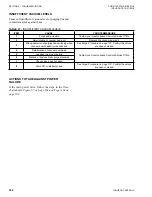
Page 159: ...absorber See Purge Procedure on page 130 Even if the automatic purge unit is installed purge from the lower pressure side absorber manually 5 Chilled water outlet temperature controller is not set pro...

Page 160: ...lights or if the vacuum level of the purge line does not reach the specified level during the vacuum pump capacity check Table 45 VACUUM PUMP TROUBLESHOOTING ITEM CAUSE COUNTERMEASURE 1 Deterioration...

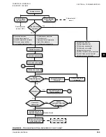
Page 161: ...roller valve and check the strainer for clogging Check the capacity of the cooling tower See Purge Procedure on page 130 Check the capacity of the vacuum pump Check the purge unit for trouble Purge ai...

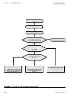
Page 162: ...mp oil 3 Wrong operation of purging line switching when vacuum pump capacity was checked See Purge Procedure on page 130 Confirm the valves are open or closed 4 Deterioration of vacuum pump belt Conta...

Page 163: ...t issues No Yes Dilution time up Yes Stop with dilution operation Hot water pump stop Hot water valve close Dilution time increasing Solution Refrigerant Pump stop Dilution time stops increasing Solut...

Page 164: ...tart using the Control Panel located on the chiller Monitor until chiller returns to normal operation Purge directly from the absorber Stop the machine to ensure the dilution operation takes place Pow...

Page 165: ...suit able and safe manner 7 Isolate the unit heat exchanger from the external water systems and drain the heat exchanger sec tion of the system If no isolation valves are in stalled it may be necessar...

Page 166: ...m Pennsylvania USA 17349 800 861 1001 Subject to change without notice Printed in USA Copyright by Johnson Controls 2018 www johnsoncontrols com ALL RIGHTS RESERVED Form 155 30 ICOM2 EN UL 1218 Issue...

Reviews: