


JOHNSON CONTROLS
106
FORM 155.30-ICOM2.EN.UL
ISSUE DATE: 12/21/2018
SECTION 6 – OPERATION
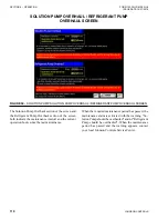
An illustration of the system shows the following in-
formation:
• 3-way valve control output
• Chilled water entering / leaving temperature
• Cooling water entering / leaving temperature
• Hot water entering / leaving temperature
• Refrigerant temperature
• Absorber temperature
• Generator temperature
• Purge tank pressure
• Generator pressure
• Generator concentration
This screen shows the status of the equipment in the
chiller process diagram.
Items in the chiller process diagram are:
Pump
Solution circulating pump, solution spray pump,
refrigerant pump, purge pump, chilled water
pump, cooling water pump, and hot water pump
- Flickers white during operation. Remains black
when the pump is stopped.
69WC1 or 69WC2 (option)
Differential pressure switch of chilled water
(69WC1) and cooling water (69WC2)
- White when water is flowing. Turns black when
the water is stopped.
Valve
Hot water control valve, refrigerant blow valve, or
purge tank valve
White indicates valve is shut off. Any other color
indicates the valve is open.
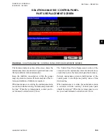
The condition lights show the current operating mode
and status of the system.
The four (4) buttons along the bottom of the Main
screen are common to many of the other screens in the
Control Panel. They all can be used to move around
and access other screen information. They are:
•
MAIN:
return to the initial screen
•
DATA:
move to the Data screen
•
FAIL
or
ALARM:
move to the Failure and Alarm
screen
•
SETTING:
move to the Setting screen


