


JOHNSON CONTROLS
124
FORM 155.30-ICOM2.EN.UL
ISSUE DATE: 12/21/2018
SECTION 6 – OPERATION
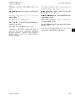
SETTING SCREEN
LD20028_UL
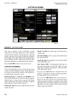
FIGURE 57 -
SETTING SCREEN
This screen displays control parameters (setting
method and each setting parameter), valve operation
(control valve mode auto / manual and valve position
setting), operation switch (forced dilution, refrigerant
pump, purge mode, and manual purge), language (Jap-
anese, English, German, Chinese, Duetsch) and other
applicable languages.) and date and time parameters.
Press the
SETTING
button to access this screen.
CONTROL PARAMETER
The Control Parameter section of the Setting screen
is used to enter parameters for the cooling operation,
such as target temperature, automatic stop temperature,
and differential to automatic restart.
Setting Method:
The
LOCAL
and
REMOTE
but-
tons control whether the set point is being set using the
Control Panel or from a remote location. The button
that is lit indicates if the set point is being set using the
Control Panel or from a remote location.
Setting Base Temp.:
the base temperature for calculat-
ing the set point
Remote Set. Diff.:
the setting range with external 4-20
mADC signal
Set Point (Display):
the set point of the chilled water
leaving temperature
Automatic Stop:
the temperature at which the chiller
will automatically stop
Auto. Restart Diff.:
The temperature difference be-
tween the temperature at which the chiller will auto-
matically stop and the temperature at which the chiller
will automatically restart.
If you press the
LOCAL
button, the entered base tem-
perature corresponds to the present target temperature.
Its temperature is shown in Set Point.
If you press the
REMOTE
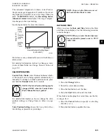
button, the setting charac-
teristics of the remote Set Point are determined based
on the setting base temperature and the remote setting
differential. The actual target temperature is calculated
depending on these settings and the remote Set Point
setting signal (4-20 mADC).


