


FORM 201.24-NM2
67
YORK INTERNATIONAL
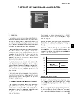
7.1 GENERAL
The microprocessor monitors leaving chilled liquid tem-
perature and adjusts the chiller cooling capacity to main-
tain this temperature within a programmed range. The
capacity is controlled by switching compressors on or off,
and by varying a load/unload current to each compressor
slide valve to adjust the capacity of the compressors.
The microprocessor controls chilled liquid temperature
through a combination of Fuzzy Logic control and in-
ternal timers. Fuzzy logic enables the microprocessor
to analyze the deviation from the setpoint and the rate
of change and determine the amount of loading and
unloading necessary to control to the desired chilled
liquid setpoint temperature.
The microprocessor also attempts to maximize effi-
ciency by spreading the cooling load between compres-
sors, minimizing compressor cycling, and optimally uti-
lizing evaporator tube surface (maximize efficiency).
This method of control is suitable for both water and
brine cooling.
Control setpoints can be programmed into the chiller
to establish the desired range of leaving chilled liquid
operating temperatures. A description of the operation
and programming follows.
7.2 CHILLED LIQUID TEMPERATURE CONTROL
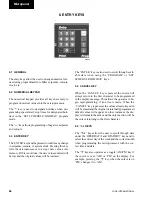
The ‘SETPOINTS’ keys are used to program the re-
quired chilled water liquid temperature for the appli-
cation. This is accomplished by programming the set-
point and the range. The range and is the maximum
acce and - deviation from setpoint.
The minimum acceptable temperature is the ‘LOWER
RANGE’ and is calculated by subtracting the ‘-’ range
from the setpoint.
The maximum acceptable temperature is the ‘UPPER
RANGE’ and is calculated by adding the ‘+’ range to
the setpoint.
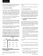
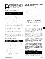
For example, if the desired setpoint temperature is 7°C
and the range is +/- 1°C, then the microprocessor will
attempt to control leaving chilled liquid temperatures
to 6°C to 8°C, as shown below:
To ensure that the chilled liquid leaving temperature
stays within the range, the microprocessor will attempt
to control the leaving temperature to the actual setpoint
temperature.
This is accomplished by analyzing the temperature er-
ror (ERROR) and the rate of change (RATE) to deter-
mine the amount of loading necessary to cool the chilled
29023a
7. SETPOINT KEYS AND CHILLED LIQUID CONTROL
FIG. 19 – SETPOINT RANGE
10°C
9°C
8°C
7°C
SETPOINT
RANGE
6°C
TEMPERATURE
5°C
4°C
7
Summary of Contents for YCWS0313SC
Page 12: ...YORK INTERNATIONAL 12 THIS PAGE INTENTIONALLY LEFT BLANK TO MAINTAIN PAGE FORMAT...
Page 36: ...YORK INTERNATIONAL 36 THIS PAGE INTENTIONALLY LEFT BLANK TO MAINTAIN PAGE FORMAT Commissioning...
Page 86: ...YORK INTERNATIONAL 86 TYPICAL CONTROL PANEL WIRING Maintenance...
Page 87: ...FORM 201 24 NM2 87 YORK INTERNATIONAL TYPICAL CONTROL PANEL WIRING LD06957 8...
Page 103: ...FORM 201 24 NM2 103 YORK INTERNATIONAL NOTES 11...