


YORK INTERNATIONAL
42
1.14 CONTROL PANEL
No controls (Relays etc.) should be mounted in any
section of the control panels. Additionally control wir-
ing not connected to the YORK Control Panel should
not be run through the Control Panel. If these precau-
tions are not followed, electrical noise could cause mal-
functions or damage to the unit and its controls.
1.15 REMOTE EMERGENCY STOP DEVICE
A remote emergency stop device can be connected to
terminals 3 and 4 in the common input supply section
after removing a link. When operated it removes the
115VAC control supply and supply to the electronics.
All devices are de-energized including compressor con-
tractors. The loss of supply to the power supply board
results in the display going off.
To conform with the requirement of EN
418 and EN 60204-1 that re-setting the
emergency stop device will not initiate
a restart, ‘POWER FAIL RESTART’
should be programmed under the
‘PROGRAM’ key to ‘MANUAL’.
‘MANUAL’ restart requires a reset us-
ing the unit ON/OFF switch under the
keypad.
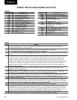
1.16 COMMON INPUT POWER SECTION VOLTAGE
FREE CONTACTS
All wiring to the power section voltage free contacts
requires a supply provided by the customer maximum
voltage 254 volts AC, 28VDC. These contacts are on
the customer relay board -ACRB in the common input
power section, the terminals being on a removable plug
for ease of wiring.
The terminal numbers are situated on
the circuit board, not the plug. The
customer must take particular care
deriving the supplies for the voltage
free terminals with regard to a com-
mon point of isolation. Thus, these cir-
cuits when used must be fed via the
common point of isolation so the volt-
age to these circuits is removed when
the common point of isolation to the
unit is opened. This common point of
isolation is not supplied by YORK.
In accordance with the National Electrical Code
(N.E.C.) it is recommended that the customer wiring
to these terminals uses orange wires. This will ensure
that circuits not switched off by the units supply dis-
connecting device are distinguished by color, so that
they can easily be identified as live even when the unit
disconnecting devices are off. The YORK voltage free
contacts are rated at 125VA. All inductive devices (re-
lays) switched by the YORK voltage free contacts must
have their coil suppressed using standard R/C suppres-
sors. If these precautions are not followed, electrical
noise could cause malfunctions or damage to the unit
and its controls.
1.17 ALARM CONTACTS
Each system has a voltage free contact which will
OPEN to signal an alarm condition whenever a system
locks out or there is a power failure. To obtain a sys-
tem alarm signal, connect live to Terminal 1 and use
terminal 8 for No. 1 system alarm and terminal 7 for
No. 2 system alarm.
1.18 CHILLED LIQUID PUMP CONTACT
YORK provides a voltage free contact terminals 5 and 6
which close to start a pump. This contact can be used as
a master start/stop for the pump in conjunction with the
daily start/stop schedule. If no schedule is set the con-
tact will close when the unit switch is set to on. The
contact must be used so that the contact can start the
pump in the event of a low temperate liquid condition.
A stop start timer is included so that the pump will not
be asked to restart within 30 seconds of stopping.
1.19 RUN CONTACT
YORK provides a run contact which closes terminals
3 and 4 to indicate that the unit is running. This contact
closes when any system runs. This contact can be used
to start the condenser pump or fan.
1.20 ANTI-RECYCLE TIMER
The programmable anti-recycle timer allows the user to
select the compressor anti-recycle time to best suit their
needs. Motor heating occurs as a result of inrush current
when the motor is started. This heat must be dissipated
before another start takes place or motor damage may
result. The anti-recycle timer assures that the motor has
sufficient time to cool before it is restarted.
Micropanel
Summary of Contents for YCWS0313SC
Page 12: ...YORK INTERNATIONAL 12 THIS PAGE INTENTIONALLY LEFT BLANK TO MAINTAIN PAGE FORMAT...
Page 36: ...YORK INTERNATIONAL 36 THIS PAGE INTENTIONALLY LEFT BLANK TO MAINTAIN PAGE FORMAT Commissioning...
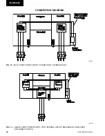
Page 86: ...YORK INTERNATIONAL 86 TYPICAL CONTROL PANEL WIRING Maintenance...
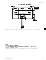
Page 87: ...FORM 201 24 NM2 87 YORK INTERNATIONAL TYPICAL CONTROL PANEL WIRING LD06957 8...
Page 103: ...FORM 201 24 NM2 103 YORK INTERNATIONAL NOTES 11...