


FORM 201.24-NM2
27
YORK INTERNATIONAL
No additional controls (relays, etc.)
should be mounted in the control
panel. Power and control wiring not
connected to the control panel should
not be run through the control panel.
If these precautions are not followed
it could lead to a risk of electrocution.
In addition, electrical noise could
cause malfunctions or damage the
unit and its controls.
After connection do not switch on
mains power to the unit until it has
been commissioned by YORK Autho-
rized personnel. Some internal com-
ponents are live when mains is
switched on.
The unit ON/OFF rocker switch on the front of the
control panel has been set in the “OFF” position at
the factory.
This switch MUST remain in the “OFF” position until
the unit is commissioned by YORK Authorized per-
sonnel. If the switch is set to the “ON” position before
commissioning then it must be reported to YORK, oth-
erwise the warranty may be invalidated.
POWER WIRING
The units are suitable for 400V, 3-
phase, 50 Hz nominal supplies only.
Minimum allowable 342V. Maximum
allowable 440V.
All electrical wiring should be carried out in accor-
dance with local regulations. Route properly sized
cables to cable entries on the bottom of the control
panel.
In accordance with National Electrical Code (N.E.C.)
it is the responsibility of the user to install overcurrent
protection devices between the supply conductors and
the power supply terminals on the unit.
To ensure that no eddy currents are set up in the metal
gland plate the cables forming each 3-phase power sup-
ply must enter via the same hole in the gland plate. If
separate entries for each cable forming the 3-phase
supplies are used, the metal gland plate must be re-
placed by a non-metallic gland plate, with due regard
given to sealing the panel to IP32 (NEMA 1).
All sources of supply to the unit must
be taken via a common points of iso-
lation (not supplied by YORK).
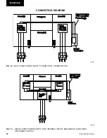
Units with Single-Point Power Supply Wiring
Models require one field provided 400VAC, 3Ø,
50 Hz ground supply to the unit with circuit protection.
Connect the 3-phase supply to the terminal block or
non-fused disconnect switch located in the common
input section using the wire sizes detailed in Section 9.
Connect the earth wire ground to the main protective
earth terminal in the common input section.
Units with Multi Point Power Supply Wiring
Units require two field provided 400VAC, 3Ø, 50 Hz sup-
plies with circuit protection and a separate control supply
with circuit protection (400VAC, 2Ø, 50 Hz + ground).
Connect each of the 3-phase supplies to the door inter-
locked circuit breakers located in the power sections,
using the wire sizes detailed in Section 9.
Connect each of the earth grounds to the main protec-
tive earth ground terminals in the power sections.
Connect the control supply to the door interlocked
emergency stop device located in the common input
section, using the wire sizes detailed in Section 9.
Connect the earth ground to the main protective earth
terminal in the common input section.
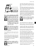
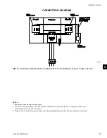
FIG. 11 – TYPICAL CONDENSER FLOW DIAGRAM
LD006600
COOLING
TOWER
THREE WAY BY-PASS VALVE
COOLING LIQUID PUMP
RECIRCULATION
LOOP
CONDENSER
4
Summary of Contents for YCWS0313SC
Page 12: ...YORK INTERNATIONAL 12 THIS PAGE INTENTIONALLY LEFT BLANK TO MAINTAIN PAGE FORMAT...
Page 36: ...YORK INTERNATIONAL 36 THIS PAGE INTENTIONALLY LEFT BLANK TO MAINTAIN PAGE FORMAT Commissioning...
Page 86: ...YORK INTERNATIONAL 86 TYPICAL CONTROL PANEL WIRING Maintenance...
Page 87: ...FORM 201 24 NM2 87 YORK INTERNATIONAL TYPICAL CONTROL PANEL WIRING LD06957 8...
Page 103: ...FORM 201 24 NM2 103 YORK INTERNATIONAL NOTES 11...