


YORK INTERNATIONAL
32
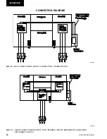
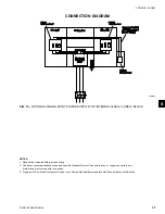
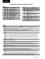
CONNECTION DIAGRAM LEGEND AND NOTES
LEGEND
DESIGNATION
DESCRIPTION
PWMC
PULSE WIDTH MODULATED CURRENT
PWMT
PULSE WIDTH MODULATED TEMPERATURE
- QCB
CIRCUIT BREAKER
- QCSD
CONTROL CIRCUIT SWITCH
DISCONNECTOR
/ESD
/ EMERGENCY STOP DEVICE
- QCSISD
COMMON SUPPLY INPUT SWITCH
DISCONNECT
- QRESB
REMOTE EMERGENCY STOP BUTTON
- QSDF
SWITCH DISCONNECT FUSED
SA
SYSTEM ALARM
- SF
FLOW SWITCH
- XVFT
VOLTAGE FREE TERMINAL BLOCK
DESIGNATION
DESCRIPTION
- ACRB
CUSTOMER RELAY BOARD
- AIOB
INPUT OUTPUT BOARD
- AMB
MICROPROCESSOR BOARD
- APB
POWER BOARD
- ARCR
REMOTE CURRENT RESET
- ARTR
REMOTE TEMPERATURE RESET
CLP
CHILLED LIQUID PUMP
CRS
COMMON RUN SIGNAL
CSI
COMMON SUPPLY INPUT
PE
PROTECTIVE EARTH
PNT
PS
POWER SECTION
NOTES
NB
NOTES
2
This port can be used for a printer - see Microprocessor Based Control System Operating Instructions for
warnings and limitations on use for this port.
10
A. PE connection for standard units when common supply input accessory is not installed.
B. PE connection for units with common supply input accessory installed.
12
For remote emergency stop button (-QRESB) facility, remove link WLK1, and connect contact across terminals 3
and 4.
13
All wiring to power section voltage free contacts requires a supply provided by the customer maximum voltage
240V. The customer must take particular care when deriving the supplies for the voltage free terminals with
regard to a common point of isolation. Thus, these circuits when used must be fed via the common point of
isolation. The voltage to these circuits is removed when the common point of isolation to the unit is opened. This
common point of isolation is not supplied by YORK. The YORK voltage free contacts are rated at 125VA. All
inductive devices (relays) switched by the YORK voltage free contacts must have their coil suppressed using
standard R/C suppressors.
14
To obtain a system alarm signal, connect live to terminal 1 and use terminal 8 for No. 1 system alarm and
terminal 7 for No. 2 system alarm.
15
Wire terminals 5 and 6 to chilled liquid pump starter, so that when the circuit between 5 and 6 is closed, the
pump must run. Contact can be used as master start/stop for pump when daily schedule test.
16
Wire terminals 3 and 4 to indicate that any systems are running. For YCWS products, contacts may be wired to
condenser pump/fan starter, so that when the circuit between 3 and 4 is closed the pump/fan must run.
18
CE units with transformer kit
19
No controls (relays etc.) should be mounted in any section of the control panel. Additionally, control wiring not
connected to the YORK control panel should not be run through the panel. If these precautions are not followed,
electrical noise could cause malfunctions or damage to the unit and its controls.
20
For single-point supply connect as shown enclosed detail. Overriding the STD. connections.
21
Use gland plate on back of logic section to avoid power cables. The voltage free contacts must be suitable for
30VDC (gold contacts recommended). If voltage free contact forms part of a relay or contactors, the coil of this
device must be suppressed by the customer using a standard R/C suppressor. The above precautions must be
taken to avoid electrical noise which could cause a malfunction or damage to the unit and its controls.
22
Connect chilled liquid flow switch as shown to provide adequate protection against loss of flow.
Installation
Summary of Contents for YCWS0313SC
Page 12: ...YORK INTERNATIONAL 12 THIS PAGE INTENTIONALLY LEFT BLANK TO MAINTAIN PAGE FORMAT...
Page 36: ...YORK INTERNATIONAL 36 THIS PAGE INTENTIONALLY LEFT BLANK TO MAINTAIN PAGE FORMAT Commissioning...
Page 86: ...YORK INTERNATIONAL 86 TYPICAL CONTROL PANEL WIRING Maintenance...
Page 87: ...FORM 201 24 NM2 87 YORK INTERNATIONAL TYPICAL CONTROL PANEL WIRING LD06957 8...
Page 103: ...FORM 201 24 NM2 103 YORK INTERNATIONAL NOTES 11...