


31
AFFINITY LOW SILL SERIES INSTALLATION MANUAL
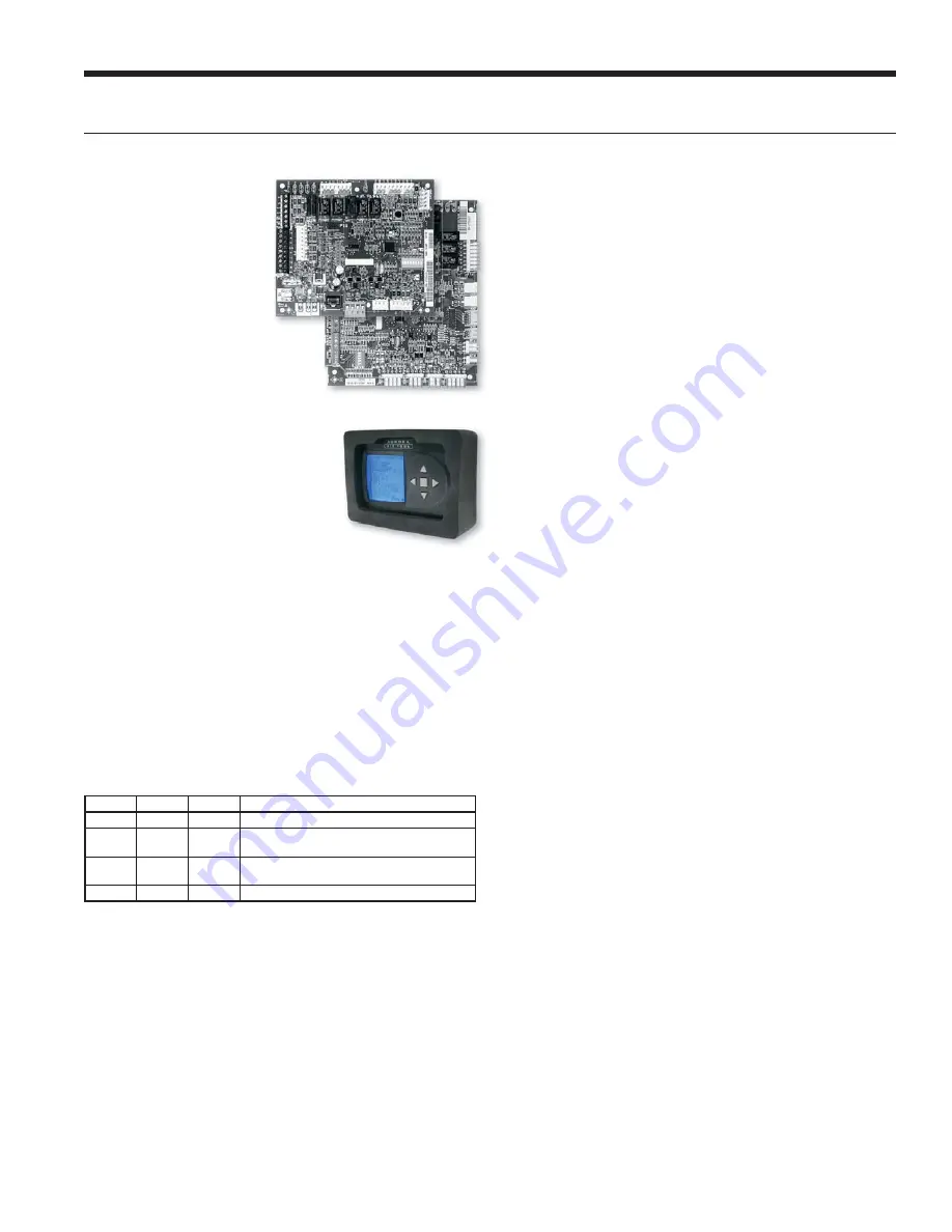
Controls cont.
Aurora ‘Advanced’ Control Features
The Aurora ‘Advanced’
Control system expands on
the capability of the Aurora
‘Base’ Control (ABC)
by adding the Aurora
Expansion Board (AXB).
All of the preceding
features of the Aurora
‘Base’ Control are included.
The following control
description is of the
additional features and
capability of the Aurora
advanced control.
It is highly recommended the
installing/servicing contractor obtain
an Aurora Interface and Diagnostic
Tool (AID) and specialized training
before attempting to install or service
an Aurora ‘Advanced’ control system.
The additional AXB features include the following:
AXB DIP Switch
DIP 1 - ID
: This is the AXB ModBus ID and should always
read On.
DIP 2 & 3 - Future Use
DIP 4 & 5 - Accessory Relay2
: A second, DIP configurable,
accessory relay is provided that can be cycled with the
compressor 1 or 2 , blower, or the Dehumidifier (DH)
input. This is to complement the Accessory 1 Relay on
the ABC board.
Position
DIP 4
DIP 5
Description
1
ON
ON
Cycles with Fan or ECM (or G)
2
OFF
ON
Cycles with CC1 first stage of compressor
or compressor spd 6
3
ON
OFF
Cycles with CC2 second stage of
compressor or compressor spd 7-12
4
OFF
OFF
Cycles with DH input from ABC board
Advanced Hot Water Generator Control
(Domestic Hot Water Option)
In lieu of the ‘Base Hot Water Generator Control’, the
Advanced features an AID Tool selectable temperature limit
and microprocessor control of the process. This will maximize
hot water generation and prevent undesirable energy use. An
alert will occur when the hot water input temperature is at
or above setpoint (100°F - 140°F) for 30 continuous seconds
(130°F is the default setting). This alert will appear as an E15
on the AID Tool and the hot water pump de-energizes. Hot
water pump operations resume on the next compressor cycle
or after 15 minutes of continuous compressor operation during
the current thermostat demand cycle. Since compressor hot
gas temperature is dependent on loop temperature in cooling
mode, loop temperatures may be too low to allow proper
heating of water. The control will monitor water and refrigerant
temperatures to determine if conditions are satisfactory for
heating water. LED1 (red LED) will flash code 15 when the
DHW limit is reached and when conditions are not favorable
for water heating. Error code 15 will also be displayed on the
AID Tool in the fault screen. This flash code is a noncritical
alert and does not necessarily indicate a problem.
Compressor Monitoring
The AXB includes two current transducers to monitor the
compressor current and starting characteristics. Open
circuits or welded contactor faults will be detected. A fault
will produce an E10 code.
IntelliZone2 Zoning Compatibility
(Optional IntelliZone2 Zoning)
A dedicated input to connect and communicate with the
IntelliZone2 (IZ2) zoning system is provided on P7. The is a
dedicated communication port using a proprietary ModBus
protocol. An AXB can be added to other selected ABC-only
systems as well. Then an advanced communicating IntelliZone2
zoning system can be added to ABC-only systems. Consult the
IntelliZone2 literature for more information.
Variable Speed Pump
This input and output are provided to drive and monitor
a variable speed pump. The VS pump output is a PWM
signal to drive the variable speed pump. The minimum and
maximum level are set using the AID Tool. 75% and 100%
are the default settings respectively. The VS data input
allows a separate PWM signal to return from the pump
giving fault and performance information. Fault received
from the variable speed pump will be displayed as E16.
Modulating Water Valve
This output is provided to drive a modulating water valve.
Through advanced design the 0-10VDC valve can be
driven directly from the VS pump output. The minimum
and maximum level are set in the same way as the VS
pump using the AID Tool. 75% and 100% are the default
settings respectively.
Loop Pump Linking
This input and output are provided so that two units can be
linked together with a common flow center. When either unit
has a call for loop pump, both unit’s loop pump relays and
variable speed pumps are energized. The flow center then can
simply be wired to either unit. The output from one unit should
be routed to the input of the other. If daisy chained up to 16
heat pumps can be wired and linked together in this fashion.
Summary of Contents for YCL09
Page 2: ......
Page 42: ...42 AFFINITY LOW SILL SERIES INSTALLATION MANUAL Notes...


