JOHNSON CONTROLS
178
FORM 150.67-NM1
ISSUE DATE: 4/28/2017
SECTION 7 – UNIT CONTROLS
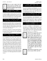
The chilled liquid is glycol. The Cooling Setpoint can be
programmed from 10 °F to 70 °F (-12.2 °C to 21.1 °C).
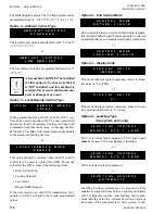
Option 4 – Ambient Control Type
A M B I E N T C O N T R O L
S T A N D A R D
The low ambient cutout is adjustable from 25 °F to 60 °F
(-3.9 °C to 15.6 °C).
or
A M B I E N T C O N T R O L
L O
W A
M
B I E N T
The low ambient cutout is programmable down to 0 °F
(-17.8 °C).
A low ambient kit MUST be installed
for this option to be chosen. If the kit
is NOT installed, and low ambient is
selected, low pressure faults and com-
pressor damage may occur.
Option 5 – Local/Remote Control Type
L O C A L / R E M O T E M O D E L
L O
C
A L
When programmed for LOCAL, an ISN or RCC con-
trol can be used to monitor only. The micro panel will
operate on locally programmed values and ignore all
commands from remote devices, or through the RS-
485 inputs. The chiller will communicate and send data
to the remote monitoring devices.
or
L O C A L / R E M O T E M O D E
R E
M
O T E
This mode should be selected when an ISN or RCC
control is to be used to control the chiller. This mode
will allow the ISN to control the following items:
•
Remote Start/Stop
•
Cooling Setpoint
•
Load Limit
•
History Buffer Request
If the unit receives no valid ISN transmission for 5
minutes, it will revert back to the locally programmed
values.
Option 6 – Unit Control Mode
C O N T R O L M O D E
R E T U R N L I Q U I D
Unit control is based on return chilled liquid tempera-
ture. Return Chilled Liquid Control can only be selected
on units that have 4 to 6 compressors (dual system units).
or
C O N T R O L M O D E
L E A V I N G L I Q U I D
Option 7 – Display Units
D I S P L A Y U N I T S
I M
P E R I A L
This mode displays system operating values in Impe-
rial units of °F or PSIG.
or
D I S P L A Y U N I T S
S I
This mode displays system operating values in Scien-
tific International Units of °C or barg.
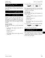
Option 8 – Lead/Lag Type
(two system units only)
L E A D / L A G C O N T R O L
M A N U A L S Y S 1 L E A D
SYS 1 selected as lead compressor. SYS 1 lead option
must
be chosen if Hot Gas Bypass is installed.
or
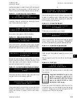
L E A D / L A G C O N T R O L
M A N U A L S Y S 2 L E A D
SYS 2 selected as lead compressor.
or
L E A D / L A G C O N T R O L
A
U T O
M
A T I C
Lead/Lag between systems may be selected to help
equalize average run hours between systems on chillers
with 2 refrigerant systems. Auto lead/lag allows auto-
matic lead/lag of the two systems based on an average
run hours of the compressors in each system. A new
Summary of Contents for YCAL0019
Page 4: ...JOHNSON CONTROLS 4 FORM 150 67 NM1 ISSUE DATE 4 28 2017 THIS PAGE INTENTIONALLY LEFT BLANK...
Page 14: ...JOHNSON CONTROLS 14 FORM 150 67 NM1 ISSUE DATE 4 28 2017 THIS PAGE INTENTIONALLY LEFT BLANK...
Page 69: ...69 JOHNSON CONTROLS SECTION 5 TECHNICAL DATA FORM 150 67 NM1 ISSUE DATE 4 28 2017 5 5...
Page 71: ...71 JOHNSON CONTROLS SECTION 5 TECHNICAL DATA FORM 150 67 NM1 ISSUE DATE 4 28 2017 5 5...
Page 229: ...229 JOHNSON CONTROLS SECTION 10 MAINTENANCE FORM 150 67 NM1 ISSUE DATE 4 28 2017 NOTES...


