


OPTIONAL ECONOMIZER RAIN HOOD
The following procedure should be used when assembling an
economizer rain hood onto a unit. The outdoor and return air
dampers, the damper actuator, the damper linkage, the outdoor
and return air divider baffles and all the control sensors are
factory mounted as part of the economizer option
All of the hood components, including the filters, the gasketing
and the hardware for assembling are packaged and located
within the unit filter secion. (See Figure 8).
1. With filter section access panel removed, take out the hood
components, filters, gasketing and hardware described
above. Remove and discard the outdoor air opening cover
on back of the unit.
2. Assemble the rain hood per the following procedures:
a) Apply gasketing to all hood components as follows:
-To the top outside surface and to the flange (toward
unit) of each side plate. Extend gasketing 1/4" be-
yond the top and bottom of the flange to insure
adequate sealing.
-To the edge and flanges (in one continuous length) on
each side of the center filter support.
-To the top flange of the bottom filter support (on the
side facing the unit).
-To the hood cover flange (only on unit sizes 10 tons
and over). (No gasketing required on this flange for unit
sizes under 10 tons.)
FIG. 5 - EXTERNAL SUPPLY CONNECTION
EXTERNAL SHUT-OFF
FIG. 6 - BOTTOM SUPPLY CONNECTION
EXTERNAL SHUT-OFF
L.P. UNITS, TANKS AND PIPING
All gas heat units are shipped from the factory equipped for
natural gas use only. The unit may be converted in the field for
use with L.P. gas with accessory kit model number 1NP0421
(U.S.A.).
All L.P. gas equipment must conform to the safety standards of
the National Fire Protection Association.
For satisfactory operation, L.P. gas pressure must be 10.5 inch
W.C at the unit under full load. Maintaining proper gas pressure
depends on three main factors:
1. The vaporization rate which depends on (a) the temperature
of the liquid and (b) the “wetted surface” area of the container
or containers.
2. The proper pressure regulation. (Two-stage regulation is
recommended from the standpoint of both cost and effi-
ciency.)
3. The pressure drop in the lines between regulators and
between the second stage regualtor and the appliance. Pipe
size required will depend on the length of the pipe run and
the total load of all appliances.
Complete information regarding tank sizing for vaporization,
recommended regulator settings, and pipe sizing is available
from most regulator manufacturers and L.P. gas suppliers.
L.P. gas is an excellent solvent and special pipe compound must
be used when assembling piping for this gas as it will quickly
dissolve white lead or most standard commercial compounds.
Shellac base compunds such as Rectorseal #5 are satisfactory
for this type of gas.
Check all connections for leaks when piping is completed, using
a soap solution. NEVER USE A FLAME.
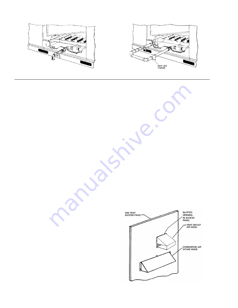
VENT AND COMBUSTION AIR HOODS
The vent and combustion air hoods (with screens) are shipped
attached to the blower housing in the blower compartment.
These hoods must be installed to assure proper unit function.
Both hoods must be fastened to the outside of the gas heat
access panel with the screws provided in the bag also attached
to the blower housing.
The screen for the combustion air intake hood is secured to the
inside of the access panel opening with three fasteners and the
screws used for mounting the hood to the panel. The top flange
of this hood slips in under the top of the access panel opening
when installing. Refer to Figure 7.
The vent hood is installed by inserting the top flange of the hood
into the slotted opening in the access panel, positioning the vent
screen between the hood flanges and the access panel, and
securing in place.
FIG. 7 - VENT AND COMBUSTION AIR HOODS
530.22-N4Y
6
Unitary Products Group