background image

2. When required by local codes, a manual shut-off valve may

have to be installed outside of the unit.

3. Use wrought iron or steel pipe for all gas lines. Pipe dope

should be applied sparingly to male threads only.

WARNING: Natural gas may contain some propane. Propane,

being an excellent solvent, will quickly dissolve white
lead or most standard commercial compounds.
Therefore, a special pipe compound must be applied
when wrought iron or steel pipe is used. Shellac base
compounds such as Gaskolac or Stalastic, and com-
pounds such as Rectorseal #5, Cyde’s or John
Crane may be used.

4. All piping should be cleaned of dirt and scale by hammering

on the outside of the pipe and blowing out the loose dirt and
scale. Before initial start-up, be sure that all of the gas lines
external to the unit have been purged of air.

5. The gas supply should be a separate line and installed in

accordance with all safety codes as prescribed under “Limi-
tations”. After the gas connections have been completed,
open the main shut-off valve admitting 

normal gas pressure

to the mains. Check all joints for leaks with soap solution or
other material suitable for the purpose. NEVER USE A
FLAME.

6. The furnace and its individual manual shut-off valve must be

disconnected from the gas supply piping system during any
pressure testing of that system at test pressures in excess of
1/2 psig (3.48kPa).
The furnace must be isolated from the gas supply piping
system by closing the individual manual shuff-off valve during
any pressure testing of the gas supply system at test
pressures equal to or less than 1/2 psig (3.48kPa).

7. A 1/8 inch NPT plugged tapping, accessible for test gage

connection, must be installed immediately upstream of the
gas supply connection to the furnace.

COMBUSTION DISCHARGE

The products of combustion are discharged horizontally through
a screened (hooded) opening on the upper gas heat access
panel.

GAS PIPING

Proper sizing of gas piping depends on the cubic feet per hour
of gas flow required, specific gravity of the gas and the length
of run. “National Fuel Gas Code” Z223.1 should be followed in
all cases unless superseded by local codes or gas company
requirements. Refer to Table 3.
The heating value of the gas may differ with locality. The value
should be checked with the local gas utility.

NOTE: There may be a local gas utility requirement specifying

a minimum diameter for gas piping. All units require a
1/2 or 3/4 inch pipe connection at the gas valve.

GAS CONNECTION

The gas supply line can be routed through the knockouts located
on the front of the unit or through the opening provided in the
unit’s base. Refer to Figure 10 to locate these access openings.
Typical supply piping arrangements are shown in Figures 5 and
6. All pipe nipples, fittings and the gas cock are field-supplied.
A gas piping kit (1GP0402) is available for bottom supply with
external shutoff.

Two grommets are shipped in the blower compartment (in parts
bag taped to the blower housing) of every unit with gas heat and
should be used in the knockouts when the gas piping penetrates
the front of the unit.

After the gas supply piping has been installed, the bottom
opening should be sealed to prevent water from leaking into the
building.

Gas piping recommendations:

1. A drip leg and a ground joint union must be installed in the

gas piping.

Input

Capacity,

(Mbh)

Output

Capacity,

(Mbh)

Available on

Models

Gas Rate

1

(Ft.

3

/Hr.)

Temp. Rise 

°

F

At Full Input 

2

Min.

Max.

163

130

7

1

2

 Ton

152

30

60

204

163

7

1

2

 - 12-1/2 Ton

190

30

60

245

198

10 & 12-1/2 Ton

228

30

60

NOTE: Gas Heaters are shipped available for natural gas, but can be converted to L.P. with
            Kit Model No. 1NP0421 (USA). All furnaces meet the latest California seasonal
             efficiency requirements.

1

Based on 1075 Btu/Ft

3

.

2

The air flow must be adjusted to obtain a temperature rise within the range shown.

TABLE 2 - GAS HEAT APPLICATION DATA

Length in Feet

Nominal Iron Pipe Size

1/2 in.

3/4 in.

1 in.

1-1/4 in.

10
20
30
40
50
60
70
80
90

100

132

92
73
63
56
50
46
43
40
38

278
190
152
130

115

105

96
90
84
79

520
350
285
245
215
195
180
170
160
150

1,050

730
590
500
440
400
370
350
320
305

Maximum capacity of pipe in cubic feet of gas per hour. (Based upon a pressure drop of 0.3
inch water column and 0.6 specific gravity gas).

TABLE 3 - PIPE SIZING

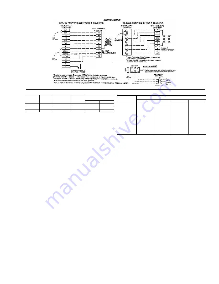
FIG. 4 - TYPICAL FIELD WIRING

530.22-N4Y

Unitary Products Group

5

Summary of Contents for SUNLINE PLUS D1EG090

Page 1: ... Manual for complete listing of replacement parts on this equipment All forms referenced in this instruction may be ordered from Publications Distribution Center Unitary Products Group P O Box 1592 York Pa 17405 APPROVALS Design certified by U L as follows 1 For use as a forced air furnace with cooling unit 2 For outdoor installation only 3 For installation on combustible material 4 For use with n...

Page 2: ...ES No Description Page 1 Unit Application Data 3 2 Gas Heat Application Data 5 3 Pipe Sizing 5 4 Physical Data 8 5 Supply Air Blower Performance 10 6 Accessory Static Resistances 11 7 Blower Motor and Drive Data 11 8 Electrical Data 11 9 Limit Control Setting 12 10 Blower Motor Pulley Adjustment 14 11 Gas Rate Cubic Feet Per Hour 15 FIGURES No Description Page 1 Center of Gravity 3 2 Barometric Re...

Page 3: ...S DISTRIBUTED EQUALLY ON THE CABLES SO THAT IT WILL LIFT EVENLY Units may also be moved or lifted with a forklift Slotted openings in the base rails are provided for this purpose LENGTH OF FORKS MUST BE A MINIMUM OF 54 Remove the nesting brackets from the four corners on top of the unit All screws that are removed when taking these brackets off must be replaced on the unit CAUTION An adhesive back...

Page 4: ...s provided by the following removable panels Compressor compartment Burner compartment Two panels Blower compartment Main control box Filter compartment Refer to Figure 10 for location of these access panels CAUTION Make sure that all screws are replaced on the unit to maintain an air tight seal THERMOSTAT The room thermostat should be located on an inside wall approximately 56 above the floor whe...

Page 5: ...ode Z223 1 should be followed in all cases unless superseded by local codes or gas company requirements Refer to Table 3 The heating value of the gas may differ with locality The value should be checked with the local gas utility NOTE There may be a local gas utility requirement specifying a minimum diameter for gas piping All units require a 1 2 or 3 4 inch pipe connection at the gas valve GAS CO...

Page 6: ...per gas pressure depends on three main factors 1 The vaporization rate which depends on a the temperature of the liquid and b the wetted surface area of the container or containers 2 The proper pressure regulation Two stage regulation is recommended from the standpoint of both cost and effi ciency 3 The pressure drop in the lines between regulators and between the second stage regualtor and the ap...

Page 7: ... using 6 gasketed screws in each side plate 4 Secure the flange on the hood cover to the duct panel with 3 screws Use holes in the cover flange as a template and drill 3 holes 9 64 dia 26 drill into the duct panel 5 Insert two 2 1 filters into the center of the hood coming to rest in the center filter support at the back of the hood Press filters up against the filter guide angles on the side plat...

Page 8: ...OR COIL ROWS DEEP 4 3 4 FINS PER INCH 15 15 15 FACE AREA Sq Ft 7 8 10 9 13 4 OUTDOOR FAN Two Per Unit PROPELLER DIA in 24 ea 24 ea 24 ea FAN MOTOR HP 1 2 ea 1 2 ea 3 4 ea NOM CFM TOTAL 2900 ea 3600 ea 4400 ea CONDENSER COIL ROWS DEEP 3 2 3 FINS PER INCH 13 18 13 FACE AREA Sq Ft 16 7 24 0 29 3 AIR FILTERS SEE NOTE QUANTITY PER UNIT 12 X 24 X 2 2 QUANTITY PER UNIT 16 X 24 X 2 2 2 3 QUANTITY PER UNIT...

Page 9: ...CONDENSER COIL DETAIL X SIDE SUPPLY AND RETURN AIR OPENINGS CLEARANCES Front 24 Back 12 Less Economizer 36 With Economizer Left Side Filter Access 24 Less Economizer 54 With Economizer Right Side Cond Coil 24 Below Unit1 20 Above Unit2 72 with 36 maximum Horizontal Overhang For Condenser Air Discharge 1 Locate unit so that the vent air outlet hood is at least Three 3 feet above any forced air inle...

Page 10: ... 39 1 80 1 68 0 02 2 05 1 91 915 1 10 1 55 1 45 0 87 1 76 1 64 0 57 1 98 1 85 0 21 2 23 2 08 950 1 29 1 68 1 57 1 06 1 91 1 78 0 77 2 14 2 00 0 40 2 43 2 27 0 04 2 72 2 54 1000 1 47 1 83 1 71 1 26 2 07 1 93 0 97 2 33 2 17 0 63 2 62 2 45 0 29 2 91 2 72 1050 1 67 1 98 1 84 1 47 2 25 2 10 1 19 2 55 2 37 0 84 2 86 2 67 0 49 3 17 2 96 1090 1 86 2 12 1 97 1 66 2 41 2 24 1 40 2 72 2 54 1 04 3 06 2 86 MOD...

Page 11: ...loss of refrigerant charge If either one of the above safety controls opens that individual refrigerant system will be locked out The other refrigerant system will continue in operation unless it too is effected by the same fault The lock out of either system can be reset by opening the 24V circuit either at the room thermostat or at the unit disconnect OPERATION TABLE 6 ACCESSORY STATIC RESISTANC...

Page 12: ...nd 3M relays SAFETY CONTROLS The control circuit includes the following safety controls 1 Limit Control LS This control is located inside the heat exchanger compartment and is set to open at the temperature indicated in Table 9 It resets automatically The limit switch operates when a high temperature condition caused by inadequate supply air flow occurs thus shutting down the ignition control and ...

Page 13: ...r adjusting screw on the automatic gas valve Refer to Figure 12 Adjust as follows 1 Remove the cap on the regulator It s located next to the push on electrical terminals 2 To decrease the gas pressure turn the adjusting screw counterclockwise 3 To increase the gas pressure turn the adjusting screw clockwise NOTE The correct manifold pressure for these furnaces is 4 1 IWG 0 3 PILOT CHECKOUT The pil...

Page 14: ...The tubes must be inserted and held in a position perpendicular to the air flow so that velocity pres sure will not affect the static pressure readings 3 Using an inclined manometer determine the pressure drop across a dry indoor coil Since the moisture on an indoor coil may vary greatly measuring the pressure drop across a wet coil under field conditions would be inaccurate To assure a dry coil t...

Page 15: ...al input is not within 5 of the furnace rating with allowance being made for the permissible range of the regulator setting replace the orifice spuds with spuds of the proper size NOTE To find the Btu input multiply the number of cubic feet of gas consumed per hour by the Btu content of the gas in your particular locality contact your gas company for this information it varies widely from city to ...

Page 16: ... applied along top of the burner COMBUSTION AIR DISCHARGE Visually inspect discharge outlet periodically to make sure that the buildup of soot and dirt is not excessive If necessary clean to maintain adequate combustion air discharge CLEANING FLUE PASSAGES AND HEATING ELEMENTS With proper combustion adjustment the heating element of a gas fired furnace will seldom need cleaning If the element shou...

Page 17: ...position a The draft motor has inherent protection If the motor shell is hot to the touch wait for the internal overload to reset b If the motor shell is cold with the room thermostat calling for heat check for line voltage at the motor s Mate N Lok connector attached to the evaporator partition If line voltage is present replace the draft motor c If line voltage is not present check for line volt...

Page 18: ...he pilot burner is aligned properly with the carryover as described in PILOT CHECKOUT b Make sure that the carryovers on adjoining burners are screwed fast and are level with respect to one another 9 Main burners light but exhibit erratic flame characteristics a Adjust air shutters as described in BURNER AIR SHUTTERADJUSTMENT b Check the main burner orifices for obstruction and alignment Removal p...

Page 19: ...530 22 N4Y Unitary Products Group 19 ...

Page 20: ...e SBY 530 22 N4Y Unitary Products Group P O Box 1592 York Pennsylvania USA 17405 1592 Subject to change without notice Printed in U S A Copyright by York International Corporation 1995 All Rights Reserved ...

Reviews: