background image

COOLING SYSTEM

The cooling section is a complete factory package utilizing an
air-cooled condenser. The system is factory-charged with
Refrigerant-22. The compressors are hermetically sealed and
internally sprung and base mounted on spring isolators.
The compressors also have inherent (internal) protection. If
there is an abnormal temperature rise in a compressor, the
protector will open to shut down the compressor.

PRELIMINARY OPERATION COOLING

After installation has been completed, energize the crankcase
heaters for at least four hours before operating unit. After this
initial warm-up, the compressors should be given three false
starts (energized just long enough to make a few revolutions)
with 5-7 minutes delay between each start before being put into
full time service. (Not applicable on 10 ton units.)

NOTE: Prior to each cooling season, the crankcase heaters

must be energized at least 10 hours before system is
put into operation.

COOLING SEQUENCE OF OPERATION

When the thermostat calls for “first-stage” cooling, the low
voltage control circuit from “R” to “G” and “Y1" (wiring
schematic) is completed to energize compressor #1,
condenser fan motor #1 and blower motor simultaneously.

When the thermostat calls for “2nd-stage” cooling, the low
voltage control circuit from “R” to “Y2" is completed to energize
compressor #2 and condenser fan motor #2.
After the thermostat is satisfied and opens, all components
likewise stop simultaneously.
CONTINUOUS BLOWER - Continuous blower operation is
possible by closing the R to G circuit on the thermostat.

SAFETY CONTROLS

Each refrigerant system is equipped with the following safety
controls:

1. A Suction Line Freezestat to protect against low evaporator

temperatures due to a low air flow or a low return air
temperature.

2. A High Pressure Cutout Switch to protect against excessive

discharge pressures due to a blocked condenser coil or a
condenser motor failure.

3. A Low Pressure Switch to protect against loss of refrigerant

charge.

If either one of the above safety controls opens, that individual
refrigerant system will be locked out. The other refrigerant
system will continue in operation unless it too is effected by the
same fault. The lock out of either system can be reset by
opening the 24V circuit either at the room thermostat or at the
unit disconnect.

OPERATION

TABLE 6 - ACCESSORY STATIC RESISTANCES*

DESCRIPTION

EXTERNAL STATIC PRESSURE DROP - RESISTANCE, IWG

CFM

2250

3000

4000

5000

6000

Economizer/Motorized Damper

0.02

0.02

0.03

0.05

0.07

*Deduct these resistance values from the available external static pressure shown in the respective Blower Performance Table.
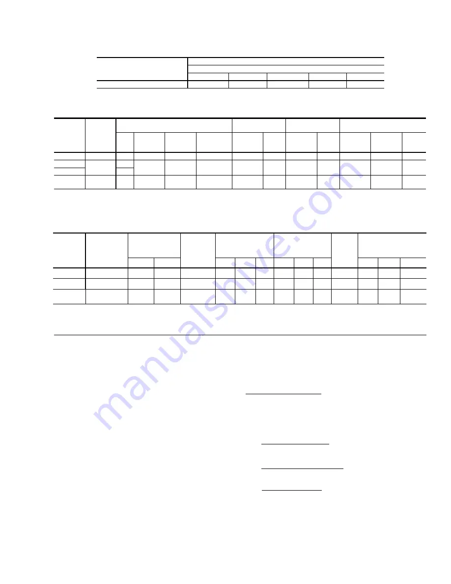
MODELS

BLOWER

RANGE

(RPM)

MOTOR*

ADJUSTABLE

MOTOR PULLEY

FIXED

BLOWER PULLEY

BELTS

HP

SERVICE

FACTOR

FRAME

SIZE

EFFICIENCY

(%)

PITCH

DIA.
(IN.)

BORE

(IN.)

PITCH

DIA.
(IN.)

BORE

(IN.)

PITCH

LENGTH

(IN.)

DESIG-

NATION

QTY

DEG090

975-1220

2

1.20

56

82.0

3.4 - 4.4

7/8

6.2

1

50.3

A49

1

DEG120

860-1090

2, 3

1.20

56

82.0

3.4 - 4.4

7/8

7.0

1

57.3

A56

1

DEG150

3

DEG150

960-1140

5

1.15

184

82.0

4.9 - 5.9

1-1/8

8.9

1

62.8

BX61

(Notched)

1

*

All motors are 1750 RPM, have solid bases and are inherently protected. These motors can be selected to operate into their service factor because they are located in the moving air,

  upstream of any heating device.

TABLE 7 - BLOWER MOTOR AND DRIVE DATA

MODEL

DEG

POWER

SUPPLY

COMPRESSOR

(#1 and #2)

OUTDOOR

FAN

MOTOR,

(#1 & #2)

FLA

EACH

SUPPLY

AIR

BLOWER

MOTOR,

FLA

TOTAL

UNIT

AMPACITY,

AMPS

MAX.

FUSE

SIZE,

1

AMPS

MIN.

WIRE

SIZE,2

AWG

RLA

EACH

LRA

EACH

2HP

3HP

5 HP

2HP

3HP

5 HP

2HP

3HP

5 HP

090

208/230-3-60

460-3-60

14.1

7.1

130

64

2.3
1.3

7.5
3.4

-
-

-
-

43.8
21.9

-
-

-
-

50
25

8

10

-
-

-
-

120

208/230-3-60

460-3-60

19.5
10.0

123

62

2.3
1.3

7.5
3.4

10.6

4.8

-
-

56.0
28.5

59.1
29.9

-
-

70
35

6
8

6
8

-
-

150

208/230-3-60

460-3-60
575-3-60

20.7
10.0

8.2

156

70
54

3.5
2.5
2.5

-
-
-

10.6

4.8
3.9

15.1

7.5
5.9

-
-
-

64.2
32.3
27.4

68.7
35.0
29.4

80

40/45

35

-
-
-

6
8
8

4
8
8

NOTES:

1. Dual element, time delay type. Amps shown as "40/45" indicates rating for 
    LO HP/HI HP, respectively. Maximum HACR breaker of the same AMP size is applicable.
2. Based on 75

°

C copper conductors.

TABLE 8 - ELECTRICAL DATA

530.22-N4Y

Unitary Products Group

11

Summary of Contents for SUNLINE PLUS D1EG090

Page 1: ... Manual for complete listing of replacement parts on this equipment All forms referenced in this instruction may be ordered from Publications Distribution Center Unitary Products Group P O Box 1592 York Pa 17405 APPROVALS Design certified by U L as follows 1 For use as a forced air furnace with cooling unit 2 For outdoor installation only 3 For installation on combustible material 4 For use with n...

Page 2: ...ES No Description Page 1 Unit Application Data 3 2 Gas Heat Application Data 5 3 Pipe Sizing 5 4 Physical Data 8 5 Supply Air Blower Performance 10 6 Accessory Static Resistances 11 7 Blower Motor and Drive Data 11 8 Electrical Data 11 9 Limit Control Setting 12 10 Blower Motor Pulley Adjustment 14 11 Gas Rate Cubic Feet Per Hour 15 FIGURES No Description Page 1 Center of Gravity 3 2 Barometric Re...

Page 3: ...S DISTRIBUTED EQUALLY ON THE CABLES SO THAT IT WILL LIFT EVENLY Units may also be moved or lifted with a forklift Slotted openings in the base rails are provided for this purpose LENGTH OF FORKS MUST BE A MINIMUM OF 54 Remove the nesting brackets from the four corners on top of the unit All screws that are removed when taking these brackets off must be replaced on the unit CAUTION An adhesive back...

Page 4: ...s provided by the following removable panels Compressor compartment Burner compartment Two panels Blower compartment Main control box Filter compartment Refer to Figure 10 for location of these access panels CAUTION Make sure that all screws are replaced on the unit to maintain an air tight seal THERMOSTAT The room thermostat should be located on an inside wall approximately 56 above the floor whe...

Page 5: ...ode Z223 1 should be followed in all cases unless superseded by local codes or gas company requirements Refer to Table 3 The heating value of the gas may differ with locality The value should be checked with the local gas utility NOTE There may be a local gas utility requirement specifying a minimum diameter for gas piping All units require a 1 2 or 3 4 inch pipe connection at the gas valve GAS CO...

Page 6: ...per gas pressure depends on three main factors 1 The vaporization rate which depends on a the temperature of the liquid and b the wetted surface area of the container or containers 2 The proper pressure regulation Two stage regulation is recommended from the standpoint of both cost and effi ciency 3 The pressure drop in the lines between regulators and between the second stage regualtor and the ap...

Page 7: ... using 6 gasketed screws in each side plate 4 Secure the flange on the hood cover to the duct panel with 3 screws Use holes in the cover flange as a template and drill 3 holes 9 64 dia 26 drill into the duct panel 5 Insert two 2 1 filters into the center of the hood coming to rest in the center filter support at the back of the hood Press filters up against the filter guide angles on the side plat...

Page 8: ...OR COIL ROWS DEEP 4 3 4 FINS PER INCH 15 15 15 FACE AREA Sq Ft 7 8 10 9 13 4 OUTDOOR FAN Two Per Unit PROPELLER DIA in 24 ea 24 ea 24 ea FAN MOTOR HP 1 2 ea 1 2 ea 3 4 ea NOM CFM TOTAL 2900 ea 3600 ea 4400 ea CONDENSER COIL ROWS DEEP 3 2 3 FINS PER INCH 13 18 13 FACE AREA Sq Ft 16 7 24 0 29 3 AIR FILTERS SEE NOTE QUANTITY PER UNIT 12 X 24 X 2 2 QUANTITY PER UNIT 16 X 24 X 2 2 2 3 QUANTITY PER UNIT...

Page 9: ...CONDENSER COIL DETAIL X SIDE SUPPLY AND RETURN AIR OPENINGS CLEARANCES Front 24 Back 12 Less Economizer 36 With Economizer Left Side Filter Access 24 Less Economizer 54 With Economizer Right Side Cond Coil 24 Below Unit1 20 Above Unit2 72 with 36 maximum Horizontal Overhang For Condenser Air Discharge 1 Locate unit so that the vent air outlet hood is at least Three 3 feet above any forced air inle...

Page 10: ... 39 1 80 1 68 0 02 2 05 1 91 915 1 10 1 55 1 45 0 87 1 76 1 64 0 57 1 98 1 85 0 21 2 23 2 08 950 1 29 1 68 1 57 1 06 1 91 1 78 0 77 2 14 2 00 0 40 2 43 2 27 0 04 2 72 2 54 1000 1 47 1 83 1 71 1 26 2 07 1 93 0 97 2 33 2 17 0 63 2 62 2 45 0 29 2 91 2 72 1050 1 67 1 98 1 84 1 47 2 25 2 10 1 19 2 55 2 37 0 84 2 86 2 67 0 49 3 17 2 96 1090 1 86 2 12 1 97 1 66 2 41 2 24 1 40 2 72 2 54 1 04 3 06 2 86 MOD...

Page 11: ...loss of refrigerant charge If either one of the above safety controls opens that individual refrigerant system will be locked out The other refrigerant system will continue in operation unless it too is effected by the same fault The lock out of either system can be reset by opening the 24V circuit either at the room thermostat or at the unit disconnect OPERATION TABLE 6 ACCESSORY STATIC RESISTANC...

Page 12: ...nd 3M relays SAFETY CONTROLS The control circuit includes the following safety controls 1 Limit Control LS This control is located inside the heat exchanger compartment and is set to open at the temperature indicated in Table 9 It resets automatically The limit switch operates when a high temperature condition caused by inadequate supply air flow occurs thus shutting down the ignition control and ...

Page 13: ...r adjusting screw on the automatic gas valve Refer to Figure 12 Adjust as follows 1 Remove the cap on the regulator It s located next to the push on electrical terminals 2 To decrease the gas pressure turn the adjusting screw counterclockwise 3 To increase the gas pressure turn the adjusting screw clockwise NOTE The correct manifold pressure for these furnaces is 4 1 IWG 0 3 PILOT CHECKOUT The pil...

Page 14: ...The tubes must be inserted and held in a position perpendicular to the air flow so that velocity pres sure will not affect the static pressure readings 3 Using an inclined manometer determine the pressure drop across a dry indoor coil Since the moisture on an indoor coil may vary greatly measuring the pressure drop across a wet coil under field conditions would be inaccurate To assure a dry coil t...

Page 15: ...al input is not within 5 of the furnace rating with allowance being made for the permissible range of the regulator setting replace the orifice spuds with spuds of the proper size NOTE To find the Btu input multiply the number of cubic feet of gas consumed per hour by the Btu content of the gas in your particular locality contact your gas company for this information it varies widely from city to ...

Page 16: ... applied along top of the burner COMBUSTION AIR DISCHARGE Visually inspect discharge outlet periodically to make sure that the buildup of soot and dirt is not excessive If necessary clean to maintain adequate combustion air discharge CLEANING FLUE PASSAGES AND HEATING ELEMENTS With proper combustion adjustment the heating element of a gas fired furnace will seldom need cleaning If the element shou...

Page 17: ...position a The draft motor has inherent protection If the motor shell is hot to the touch wait for the internal overload to reset b If the motor shell is cold with the room thermostat calling for heat check for line voltage at the motor s Mate N Lok connector attached to the evaporator partition If line voltage is present replace the draft motor c If line voltage is not present check for line volt...

Page 18: ...he pilot burner is aligned properly with the carryover as described in PILOT CHECKOUT b Make sure that the carryovers on adjoining burners are screwed fast and are level with respect to one another 9 Main burners light but exhibit erratic flame characteristics a Adjust air shutters as described in BURNER AIR SHUTTERADJUSTMENT b Check the main burner orifices for obstruction and alignment Removal p...

Page 19: ...530 22 N4Y Unitary Products Group 19 ...

Page 20: ...e SBY 530 22 N4Y Unitary Products Group P O Box 1592 York Pennsylvania USA 17405 1592 Subject to change without notice Printed in U S A Copyright by York International Corporation 1995 All Rights Reserved ...

Reviews: