035-17480-000 Rev. A (800)
16
Unitary Products Group
VENT PIPE SIZING (1-PIPE SYSTEM)
Refer to Table 5 to select the proper size piping for venting.
The size will be determined by a combination of furnace
model, total length of run, and the number of elbows required.
The following rules must also be observed.
NOTE:Furnace vent pipe connections are sized for 2-in. pipe.
Any pipe size change must be made outside the furnace cas-
ing in a vertical pipe section to allow proper drainage of vent
connections.
NOTE:An offset using two 45 degree elbows may be required
for plenum clearance when the vent is increased to 3".
1.
Long radius elbows are required for all units.
2.
Elbows are assumed to be 90 degrees. Two 45 degree
elbows count as one 90 degree elbow.
3.
One Vent terminal elbow is already accounted for and
should not be counted in the allowable total indicated in
the table. See “VENT TERMINAL LOCATION
CLEARANCES" Section on page 16 . This part is shown
shaded.
4.
All vent pipe and fittings must conform to American
National Standards Institute (ANSI) standards and Amer-
ican Society for Testing and Materials (ASTM) standards
D1785 (Schedule 40 PVC), D2665 (PVC-DWV), F891
(PVC-DWV Cellular Core), D2241 (SDR-21 and SDR-26
PVC), D2261 (ABS-DWV), or F628 (Schedule 40 ABS.
Pipe cement and primer must conform to ASTM Stan-
dards D2564 (PVC) or D2235 (ABS).
5.
The use of flexible connectors or no hub connectors in
the vent system is not allowed.
NOTE:If installing furnace at altitudes between 2000 - 4500
ft., intake and vent pipe length must be reduced by 10 ft. If the
installation requires the maximum allowable intake and vent
pipe length, the furnace must be converted for high altitude
operation. Refer to the proper high altitude application
instruction for details.
VENT TERMINATION (1-PIPE SYSTEM)
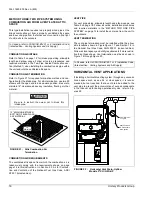
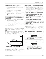
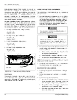
Side wall horizontal vent terminals and roof mounted vertical
terminals may be field fabricated. Standard PVC/SRD fittings
may be used. Terminal configuration must comply as detailed
in this section.
When selecting the locations for vent termination, the follow-
ing should be considered:
1.
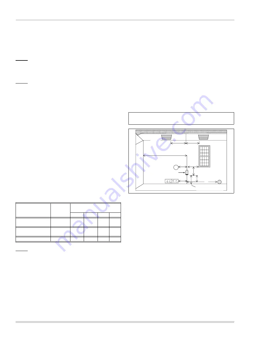
Comply with all clearance requirements. Figure 17 on
page 16.
2.
Termination should be positioned where vent vapors will
not damage plants or shrubs or air conditioning equip-
ment.
3.
Termination should be located where it will not be
affected by wind gusts, light snow, airborne leaves or
allow recirculation of flue gases.
4.
Termination should be located where it will not be dam-
aged or exposed to flying stones, balls, etc.
5.
Termination should be positioned where vent vapors are
not objectionable.
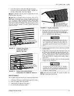
VENT TERMINAL LOCATION CLEARANCES
The vent must be installed with the following minimum clear-
ances (refer to Figure 17), and complying with local codes or
utility requirements or other authority having jurisdiction.
1.
1 foot above grade and above normal snow levels.
2.
Not above any walkway.
3.
4 feet below, 4 feet horizontally from, or 1 foot above any
door/window or gravity air inlet to the building, or from
gas or electric meters.
4.
6 feet from any inside corner formed by two exterior
walls. 10 feet is recommended where possible.
5.
At least 4 feet horizontally from any soffit or undereave
vent.
6.
10 feet from any forced air inlet to the building. Any fresh
air or make up inlet as for a dryer or furnace area is con-
sidered to be a forced air inlet.
TABLE 5: VENT PIPING / 1-PIPE SYSTEM
(ALL MODELS)
Model
Pipe Size
Max. Elbows vs. One Way Vent
Length (Ft.)
5-40
45
50
75
All Models Except:
120 / 112 / 2000 / D
2”
6
5
4
N/A
All Models Except:
120 / 112 / 2000 / D
3”
8
7
6
5
120 / 112 / 2000 / D
3” Only
6
5
4
N/A
In Canada, refer to CAN/CGA-B149.1 or.2 Installation Code
(latest edition - Venting Systems and Air Supply)
FIGURE 17 :
Minimum Vent Terminal
Clearances (1-Pipe System) - U.S. Only
INSIDE
CORNER
SOFFIT
VENTS
ELECTRIC
METER
4'
4'
4'
4'
6'
(10' RECOMMENDED)
4'
1' PLUS
SNOW CLEARANCE
4'
FORCED
AIR
INTAKE
10'
3'
FURNACE VENT


