


FORM 160.54-PW7
9
YORK INTERNATIONAL
REMOTE CURRENT LIMIT SETPOINT with 0-10VDC,
2-10 VDC, 0-20mA, 4-20mA or Pulse Width Modula-
tion Signal.
The Remote Current Limit setpoint can be reset over
the range of 100% to 30% Full Load Amps (FLA) by
supplying (by others) a 0-10VDC, 2-10VDC, 0-20mA,
4-20mA or 1 to 11 second Pulse Width Modulated
(PWM) signal to the OptiView Control Center. The
OptiView Control Center must be configured appropri-
ately to accept the desired signal type as follows:
• The appropriate Remote Mode must be selected:
Analog Remote Mode must be selected when us-
ing a voltage or current signal input. Digital Re-
mote Mode must be selected when using a PWM
input.
• If Analog Remote Mode is selected, the Remote
Analog Input Range setpoint must be set to “0-
10VDC” or “2-10VDC” as detailed below, regard-
less of whether the signal is a voltage or current
input signal type.
• Microboard Program Jumper P23 must be positioned
appropriately per the input signal type as detailed
below. It is recommended that a qualified Service
Technician position this jumper.
Important! The signal type used for
Remote Current Limit Setpoint reset
and the signal type used for Remote
Leaving Chilled Liquid Temperature
setpoint reset must be the same. For
example, if a 0-10VDC signal is be-
ing used for Remote Leaving Chilled
Liquid Temperature Reset , then a 0-
10VDC signal must be used for Re-
mote Current Limit Reset.
0-10VDC - As shown in Fig. 15, connect input to
Microboard J22-1 (signal) and J22-5 (Gnd). The setpoint
varies linearly from 100% to 30% FLA as the input var-
ies from 0-10VDC. This input will only be accepted when
Analog Remote Mode is selected, the “Remote Ana-
log Input Range” setpoint is set for 0-10 Volts, and
Microboard Program Jumper JP23 has been removed.
Calculate the setpoint for various inputs as follows:
SETPOINT (%) = 100 – (VDC X 7)
For example, if the input is 5VDC, the setpoint would
be set to 65% as follows:
SETPOINT (%) = 100 – (5 X 7) = 100 – 35 = 65%
2-10VDC - As shown in Fig. 15, connect input to
Microboard J22-1 (signal) and J22-5 (Gnd). The setpoint
varies linearly from 100% to 30% FLA as the input
varies from 2 to 10VDC. This input will only be ac-
cepted when “Analog” Remote Mode is selected, the
“Remote Analog Input Range” setpoint is set for
“2-10 Volts” and Microboard Program Jumper JP23 has
been removed. Calculate the setpoint for various inputs
as follows:
FIG. 14 – ELECTRO-MECHANICAL STARTER
MANUAL RESET OVERLOADS
The chiller compressor type deter-
mines which terminals must be used
for this feature. Failure to use the
proper terminals could result in se-
rious chiller damage!
Terminals are available for connection of the manual re-
set overloads and/or safety devices in the high voltage
Electro-Mechanical Starter for U.L. or C.S.A. approved
units having 2300 to 4160 volt motors. The appropriate
terminals must be selected based on the chiller compres-
sor type. For chillers that are not equipped with compres-
sor code “P”, use terminals 1 and 53 as shown in Figure
14. For chillers equipped with compressor code “P”, use
terminals 15 and 53 as shown in Figure 14A. Refer to
appropriate Remote Motor Starter Specification as fol-
lows: 160.45-PA5.1 (all compressors except “P”);
160.54-PW14 (chillers equipped with “P” compressors).
An opening of the contacts causes the OptiView Control
Center to display: “CYCLING SHUTDOWN – AUTO
RESTART” and “MOTOR CONTROLLER – CON-
TACTS OPEN”. To restart the chiller, reset the external
device in the Electro-mechanical Starter that caused the
shutdown. Then the unit will automatically restart.
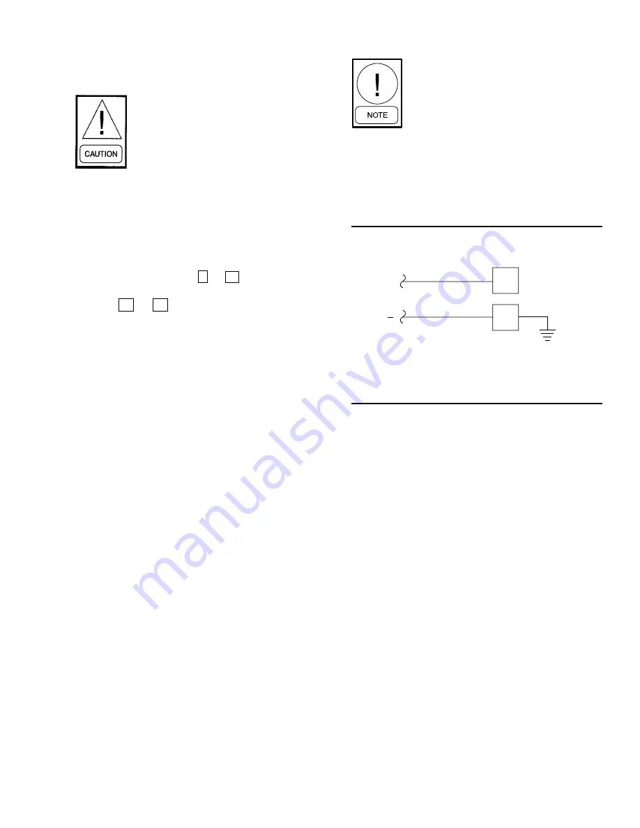
FIG. 15 – REMOTE CURRENT LIMIT SETPOINT WITH
0-10VDC OR 2-10VDC SIGNAL
SIGNAL
COMMON
5
1
+
J22
LD04498