FORM 160.54-M1(503)
21
YORK INTERNATIONAL
Early vintage chillers were equipped with BIOS eprom
031-01796-001. This eprom is no longer used. It has been
su per ced ed by BIOS eprom 031-01796-002.
IM POR -
TANT!
Eprom 031-01796-002 is not compatible with
all versions of Flash Memory Cards. Refer to Ser vice
Re place ment para graphs in this section.
When power is applied to the OptiView Control Cen-
ter fol low ing a power failure, the Micro executes the
in struc tions in the BIOS EPROM program to initialize,
con
fi
gure and start operation of certain Microboard
com po nents be fore the main program (stored in the
Flash Memory Card) is started. Depending upon the
ap pli ca tion, the Microboard could be equipped with an
EPROM that has either 128K, 256K or 512K ca pac i ty.
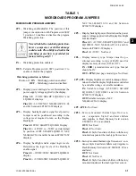
Microboard Pro gram Jumper JP38 must be po si tioned
according to the actual EPROM installed. Refer to
Ta ble 1 (Pro gram Jump ers). There are 5 steps to the
boot-up pro cess. Dur ing the boot-up process, there is
a visual in di ca tion as each step is performed, followed
by a Pass/Fail sta tus of the step. On the Microboard, a
green LED (CR17 - Pass)
fl
ash es to in di cate the step was
suc cess ful. If a step is un suc cess ful, a red LED (CR18
- Fail)
fl
ashes and the Boot-up pro cess ter mi nates. The
ex e cu tion and Pass/Fail sta tus of steps 3 through 5 are
displayed on a white Key pad Dis play Screen as they are
performed. This white dis play screen also lists the BIOS
EPROM Ver sion. The steps of the Boot-up pro cess are
as fol lows. Also, be low is listed the LED ac tiv i ty as-
sociated with each step.
BOOT-UP STEP AND DESCRIPTION
1. First initiate table complete.
Registers in the Micro are con
fi
gured to allow it to per-
form basic mem o ry read/write func tions.
2. FPGA con
fi
guration.
The Field Pro gram ma ble Gate Array (FPGA) is con-
fi
g ured to process Digital Inputs and Out puts.
3. Mini-card signature test.
A location in the Flash Memory Card that contains a code
iden ti fy ing the Man u fac tur er is compared to oth er lo ca -
tions that contain the man u fac tur er’s name. If these val ues
are the same, it is
pass
. If they are different, it is
fail
.
4. Mini-card checksum.
The
Flash
Memory Card checksum is calculated and
com pared to the checksum value that is stored in the
Card at the time the Card was initially programmed at
the YORK fac to ry. If both val ues are the same, it is
con sid ered
pass
. If the cal cu lat ed value is different than
the stored value, it is considered
fail
.
5. BRAM quick test.
Test data is written to and then read from several mem o ry
locations to ver i fy BRAM operation.
LED INDICATORS
When power is applied to the OptiView Control Cen ter,
both the red (CR18 - Fail) and green (CR17 - Pass) LEDs
si mul ta neous ly il lu mi nate for 1 sec ond, then the Boot-
up pro cess begins in the fol low ing sequence. When all
steps have been com plet ed, both LED’s illuminate and
remain il lu mi nat ed.
STEP PASS FAIL
1 Green on, Red off
Watchdog will
initiate a re-boot.
2 Green
fl
ash once
Boot-up pro cess halts.
One red
fl
ash repeating
3 Green
fl
ash once
Boot-up pro cess halts.
Two red
fl
ashes repeating
4 Green
fl
ash once
Boot-up pro cess halts.
Three red
fl
ashes repeating
5 Green
fl
ash once
Boot-up pro cess halts.
Four red
fl
ashes repeating
The
BRAM
(battery backed random access mem o ry) is
a memory device that contains a battery that pre serves
the data during power failures. It is a re place able part.
Refer to YORK Renewal Parts List Form 160.54-RP1.
It is located in socket location U52. The Micro stores
the setpoints programmed by the Op er a tor or Service
Tech ni cian, History Data and other data that requires
pres er va tion, in this device. Also, the day of week, time
of day and calendar date time-keeping are done here.
The
FPGA
(
fi
eld programmable gate array) is a single
chip consisting of generic circuits that can be con
fi
g ured
to perform a speci
fi
c task. In this OptiView Control Cen-
ter, it is used to control the Digital Outputs. As part of
the pow er-up initialization sequence, each time control
pow er is ap plied to the OptiView Control Center, the Mi-
3
Summary of Contents for MAXE OPTIVIEW YK
Page 28: ...YORK INTERNATIONAL 28 FORM 160 54 M1 503 Microboard FIG 7 MICROBOARD LD07776...
Page 60: ...YORK INTERNATIONAL 60 FORM 160 54 M1 503 Keypad FIG 32 KEYPAD CONNECTOR LD04074...
Page 61: ...FORM 160 54 M1 503 61 YORK INTERNATIONAL FIG 33 KEYPAD LD04075 LD04076 8...
Page 173: ...FORM 160 54 M1 503 173 YORK INTERNATIONAL 26 This page intentionally left blank...
Page 177: ...FORM 160 54 M1 503 177 YORK INTERNATIONAL 26 This page intentionally left blank...


