


ELECTRICAL CONNECTIONS
1. Check the electrical supply to be sure that it meets the
values specified on the unit nameplate and wiring label.
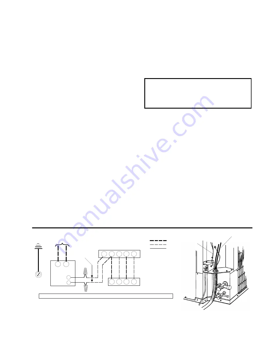
2. Route low voltage wiring into bottom of control box as
shown in Figure 8. Make low voltage wiring connections
inside the junction box.
3. The complete connection diagram and schematic wiring
label is located on the inside surface of the unit electrical
box cover. Field wiring is also shown previous page.
4. All field wiring to be in accordance with national electrical
codes.
NOTE: Power wiring, disconnect switch, and overcurrent pro-
tection to be supplied by installer. See Physical and
Electric Data Table for proper sizes. Use COPPER
CONDUCTORS ONLY.
WARNING: Unit must be grounded with a separate ground
conductor wire.
5. Install the proper size weatherproof disconnect switch out-
doors and within sight of the unit.
6. Run power wiring from the disconnect switch to the unit.
7. Install the proper size time-delay fuses or circuit
breaker,and make the power supply connections.
8. Energize the crankcase heater to save time by preheating
the compressor oil while the remaining installation is com-
pleted.
CRANKCASE HEAT
The crankcase heater is energized whenever the compressor
is not running. Check for proper operation by feeling for heat
on the compressor where the heater is installed. The heater
should be energized for at least 8 hours before the thermostat
is set to operate the compressor.
CAUTION: An attempt to start the compressor without at least
8 hours of crankcase heat will damage the com-
pressor.
A warning label with an adhesive back is supplied in the unit
installation instruction packet. This label should be attached to
the field supplied disconnect switch where it will be easily seen.
See below:
SYSTEM PRESSURE REFERENCE
The “system pressure reference charts” (See Figures 11 and
12) should only be used as a quick check of system perform-
ance. It should not be used to determine proper system charge.
1. Operate the unit for a minimum of 15 minutes before
checking system.
2. Measure Pressure at the suction and liquid fitting and
measure the Outdoor Ambient Temperature.
3. Enter the chart at the measured Suction Pressure and
Outdoor Ambient Temperature to determine the expected
Liquid Pressure.
Actual liquid pressure should agree with valves shown plus or
minus 5 psig.
POWER
WIRING
CONTROL
WIRING
FIGURE 8 - TYPICAL FIELD WIRING
C
Y
R
G
W
W
G
R
Y
CONTACTOR
TERMINALS
24 VOLT
CONTROL
WIRING
FURNACE OR AIR HANDLER
TERMINAL BLOCK
POWER
CONTROL
FACTORY
ROOM THERMOSTAT
*
* Terminal W is only required on
systems with heat.
POWER WIRING
208/230-1-60
COIL
GROUND
SCREW
ALL FIELD WIRING TO BE IN ACCORDANCE WITH NATIONAL ELECTRICAL CODE (NEC) AND/OR LOCAL CODES
ALL OUTDOOR WIRING MUST BE WEATHERPROOF. USE COPPER CONDUCTORS ONLY.
IF POWER HAS BEEN OFF FOR 8 HOURS OR LONGER,
DISCONNECT SWITCH MUST BE TURNED ON 8 HOURS
BEFORE THERMOSTAT IS SET TO “HEAT”,"COOL" OR
“AUTO”
035-03095.
IMPORTANT
550.36-N2Y
Unitary Products Group
9


