


GS 04L57B01-01EN
6
<<Contents>> <<Index>>
All Rights Reserved. Copyright © 2018, Yokogawa Electric Corporation
2018.6.12-00
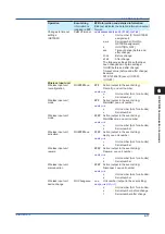
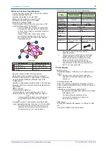
Installation Dimensions
• Wall mount (fastened with screws)
M3 screw, thread length 12 mm or more
Tightening torque: 0.6 to 0.7 N•m
• Hooked
Round wood screw: M3.5
At least 10 mm below the neck of the screw
Amount of screw showing from the wall surface to the
screw head: 3.5 to 4.0 mm
• On a desktop
• Mounted with the magnet
Minimum installation area: 50×70 mm
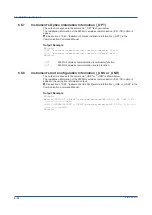
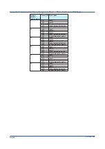
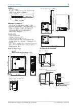
Terminal Arrangement
CH1
CH2
Functional ground terminal
Symbol
CH1
CH2
A
B (+)
b (─)
A
B (+)
b (─)
Recommended wire: AWG14-28
Recommended tightening torque: Approx. 0.2 N•m or
less
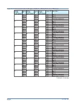
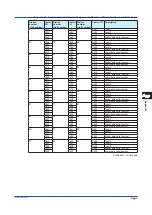
Other Functional Specifications
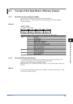
• Status display
Configuration mode, data transmission, and battery
status are indicated with LEDs (green and red).
(Indication can be turned off.)
Status
LED
Green (ST1)
Red (ST2)
Configuration mode
Green and red blinking in sync at
2 second intervals
Configuration change and
during calibration
Green and red blinking quickly
in sync
During
measurement
or data
transmission
Network
authentication
Blinking (about
0.2 second
intervals)
Off
No network
authentication
Off
Blinking (about
0.2 second
intervals)
Low battery warning
Green lit (0.1 seconds), all off
(1.9 seconds)
Red lit (0.1 seconds), all off (1.9
seconds)
The above sequence is repeated
twice, and then the LEDs are off
for 10 seconds.
Input error
Off
Lit for 0.1
seconds at
about 5 second
intervals
Mode setting error *
Repeats the sequence of green
and red lit in sync (0.1 seconds)
and all off (0.9 seconds) three
times, turns off for 2 seconds,
and repeats the entire sequence.
* For example, configuring in a mode other than measurement
mode when there is no USB connection.
• Self-diagnosis function
Transmits the following device status to the
coordinator
• Low battery warning: Low battery voltage detected.
• Critical low battery warning: Minimum drive voltage
detected. Batteries must be replaced quickly.
• Input error:
Calibration value error
A/D error
Hardware error
Memory error
Process error
• Wireless communication error: Configuration
mismatch, ambient radio environment detection
• Firmware upload
Firmware can be updated using the Wireless Input
Unit Configurator.
• Operation mode
Change between measurement and configuration
mode with a switch.
• Wireless function*
The wireless function can be turned on and off with a
switch.
*
When using the GX70SM as a standalone data
logger, you can turn off the wireless function to
prolong the battery life.
• Data logging function
Saves up to 4500 data points per channel.
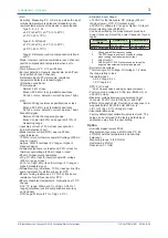
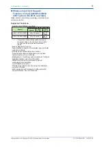
Normal Operating Conditions
• Ambient temperature: -20 to 70°C
• Temperature change rate: 10°C/h or less
• Ambient humidity: 0 to 90% RH (no condensation)
• Magnetic field: 400 A/m or less (DC and 50/60 Hz)
• Vibration:
5 ≤ f < 8.4 Hz amplitude 3.5 mm (peak)
8.4 ≤ f ≤ 160 Hz acceleration 9.8 m/s
2
or less
(excluding hooking and magnet mount)
• Shock:
Power supply on, 500 m/s
2
or less, approx. 11 ms 6
directions (± X, ± Y, ± Z) three times each
Power supply off, 98 m/s
2
or less, approx. 11 ms 6
directions (± X, ± Y, ± Z) three times each
• Altitude: 2000 m or less
• Installation location: Indoors
Transport and Storage Conditions
• Ambient temperature: -25 to 70°C
• Ambient humidity: 5 to 95% RH (no condensation)
• Vibration: 10 to 60 Hz, 4.9 m/s
2
or less
• Shock: 392 m/s
2
maximum (in packaged condition)
Summary of Contents for GX70SM
Page 1: ...User s Manual IM 04L57B01 01EN 1st Edition Model GX70SM Wireless Input Unit User s Manual ...
Page 2: ......
Page 12: ...Blank ...
Page 148: ...Blank ...
Page 168: ...Blank ...