


GS 04L57B01-01EN
3
<<Contents>> <<Index>>
All Rights Reserved. Copyright © 2018, Yokogawa Electric Corporation
2018.6.12-00
• RJC
Accuracy: Measuring 0°C or more and when the input
terminal temperature is balanced (standard mode)
(ambient temperature of the device in parentheses)
Type K, E, J, T, N:
±0.5°C (23±2°C), ±0.7°C (0 to 50°C),
±1.0°C (-20 to 70°C)
Type R, S, WRe3-25:
±1.0°C (23±2°C), ±1.4°C (0 to 50°C),
±2.0°C (-20 to 70°C)
Type B: Reference junction compensation is fixed
at 0°C.
Mode: Internal or external switchable (each channel)
(set the compensation temperature when set to
external)
• Temperature unit: °C or °F switchable
• Burnout detection: Upscale, downscale, and off can
be specified (for each channel).
Detectable inputs: Thermocouple, resistance
temperature detector, standard signal
<Detection conditions>
Thermocouple:
Normal: 2 kΩ or less
Broken: 200 kΩ or less (parallel capacitance
0.01μF or more, detection current: approx. 10μA)
RTD:
Normal: Wiring resistance specifications or less
Broken: 200 kΩ or less (parallel capacitance
0.01μF or more, detection current: approx. 10μA)
Standard signal:
Normal: Within the measuring range
Broken: Lower limit 20% and upper limit 10% of
measuring range
• Input bias current: ±10 nA or less (except when
burnout detection is set)
• Measurement current (RTD): approx. 500μA
• Input resistance:
10 MΩ or more for thermocouple/DC voltage (200 mV
range or lower)
Approx. 1 MΩ for voltage (2 V range or higher)/
standard signal
• Allowable signal source resistance: 2 kΩ or less for
thermocouple/voltage (200 mV range or less)
• Effect of signal source resistance:
±10 μV/1 kΩ or less for thermocouple/DC voltage
(200 mV range or less)
±0.15% of rdg/1 kΩ or less for voltage (2 V range or
higher)/standard signal
• Allowable wiring resistance: 10 Ω or less per line (the
same resistance for all three lines) for RTD
• Effect of wiring resistance: ±0.1°C/10 Ω (the same
resistance for all three lines) for RTD
• Effects of ambient temperature: Fluctuation per 10°C
change
DCV, TC range: Within ±(0.1% of rdg + 0.05% of
range) (reference junction compensation accuracy
not included)
RTD range: Within ±(0.1% of rdg + 0.2°C)
• Allowable input voltage:
±10 VDC for thermocouple, DC voltage (200 mV
range or lower), RTD, DI (contact input)
±30 VDC for voltage (2 V range or higher), DI (level)
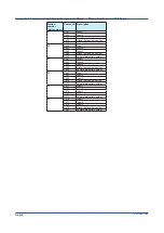
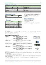
• Noise rejection ratio (50/60 Hz)
Can be specified by the measurement mode and
power frequency. Select the power frequency for your
region.
Measurement
mode
Normal mode
Common mode
Standard
1
40 dB or more
2, 3
120 dB or more
2, 4
Battery-save mode No rejection
80 dB or more
2, 4
1
Changed with the frequency setting.
2
The RTD range is a value converted to voltage
when running the measurement current.
3
50/60 Hz±0.1%.
4
50/60 Hz±0.1%, 500 Ω unbalanced, between the
negative measurement terminal and ground
• Normal mode voltage
Thermocouple, DC voltage, DI (voltage): 1.2 times
the range rating or less
Standard signal:
0.4-2 V range: 2.4 V
1-5 V range: 6 V
RTD: 5 mV peak
* 50/60 Hz, peak value including the signal component.
• Common mode voltage: 30 VAC rms (50/60 Hz) or
±60 VDC or less
• Maximum voltage between measurement input
channels: 30 VAC rms (50/60 Hz) or ±60 VDC
• Effects of magnetic field: Fluctuation in response to a
magnetic field of AC (50/60 Hz) 400 A/m is
±(0.1% of rdg + 0.1% of range) or less
• Input calibration value
Factory default input calibration value is stored. The
value can be returned to the factory default input
calibration value from the user setting.
Option
• Humidity measurement (/RH)
Measurement accuracy: ±4%RH (23±2°C, 55
±10%RH, with the temperature and humidity
balanced)
Measuring range: 0 to 90%RH
Hysteresis: ±2%RH
Resolution: 0.1%RH
Summary of Contents for GX70SM
Page 1: ...User s Manual IM 04L57B01 01EN 1st Edition Model GX70SM Wireless Input Unit User s Manual ...
Page 2: ......
Page 12: ...Blank ...
Page 148: ...Blank ...
Page 168: ...Blank ...