


C6-1
IM 34M06H45-01E
7th Edition : Aug.30, 2019-00
C6. RAS Functions of FA-bus Type 2
C6.1 System Operation with Transmission
Channel Error
C6.1.1 Run or Stop System
You can set the module to either stop the system or continue operation when a
transmission channel error occurs in an FA-bus Type 2 system.
C6.1.2 Causes of Transmission Channel Errors
A transmission channel error of an FA-bus Type 2 system may be due to the following
two reasons:
(1) Transmission cable fault
(2) Power interruption of subunit (after recognition by the system earlier)
C6.1.3 Defining System Operation (Run or Stop) in the Event
of a Transmission Channel Error
System operation in the event of a transmission channel error is determined by the [I/O
Module Error] setting and the [Subunit Communication Error] setting under [Operation
C
ontrol] in the CPU module’s configuration.
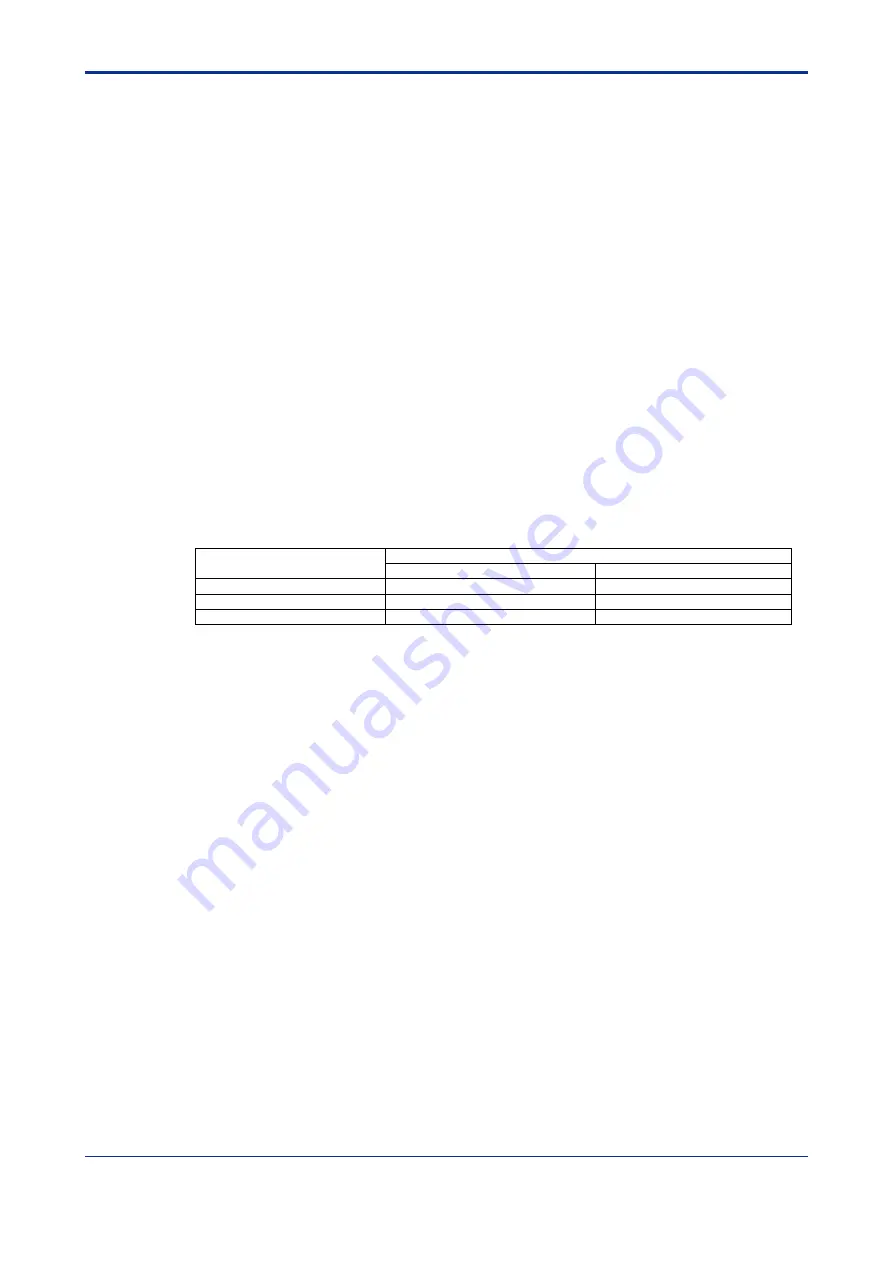
Table C6.1 System Behavior Setup
System Behavior
[Operation Control] in the CPU Module’s Configuration
I/O Module Error
Subunit Communication Error
System operation continues
Run
Run (default)
System stops
Stop (default)
Stop
See Also
C6.3.3
C6.3.3
C6.1.4 Loop Switching
In a loop configuration, when an error is detected in a transmission channel, the system
can automatically change the transmission channel configuration so as to allow normal
system operation to continue. This function is known as loop switching. To enable this
function, setup the module to continue operation in the event of a communication error
and turn off the Shutdown Output function.
A loop configuration secures two transmission loops: a primary loop and a secondary
(standby) loop. The primary loop is normally used for communications. However, the
system switches transmission loops as shown below to secure a transmission channel if
any of the following 2 events occur. (1) Cable discontinuity in the primary loop (or
secondary loop) (i.e. one of the two loops is normal); or (2) Cable discontinuity in both
the primary and secondary loops (including power interruption to a subunit).
(1) Cable discontinuity in the primary loop (or secondary loop)
In the event of cable discontinuity in either the primary loop or the secondary loop,
the system automatically switches to the loop with no cable discontinuity to secure a
transmission channel with no loss of data.
*1
(2) Cable discontinuity in both primary and secondary loops
In the event of cable discontinuity in both the primary and secondary loops, the
system automatically switches from a loop configuration to two daisy-chains to
secure a transmission channel.
*2
*1: When using F3SP05/08/21/25/35 Rev.8 or later, or F3SP22, 28, F3SP38, F3SP53, F3SP58 F3SP59, F3SP66,
F3SP67, F3SP71 or F3SP76.
*2: (1) Migration from a loop configuration to a daisy-chain configuration involves data loss.
In situations where the system continues operation, check the Subunit Line Switchover special register
and handle any loss of data accordingly.
(2) System operation after switching depends on the setting of switch SW1 located on the side of the module and
the configuration setup.
Summary of Contents for F3LR02-0N
Page 2: ...Blank Page...
Page 20: ...Blank Page...
Page 22: ...Blank Page...
Page 28: ...Blank Page...
Page 48: ...Blank Page...
Page 62: ...Blank Page...
Page 64: ...Blank Page...
Page 66: ...Blank Page...
Page 70: ...Blank Page...
Page 74: ...Blank Page...
Page 134: ...Blank Page...
Page 138: ...Blank Page...
Page 140: ...Blank Page...
Page 142: ...Blank Page...
Page 148: ...Blank Page...
Page 156: ...Blank Page...
Page 198: ...Blank Page...
Page 202: ...Blank Page...
Page 208: ...Blank Page...
Page 210: ...Blank Page...


