


ML-x17 DATA LOGGER MANUAL
Manufacturers of low power instruments
page 41
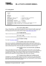
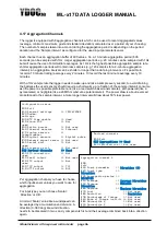
4.12.1 Sample interval
This is exactly the same feature as in other menu’s, although there is something interesting to notice
about the sample interval of a digital input (pulse sensor). With analog inputs, the sample rate defines
how many times an input is sampled. So, if your sample interval is very low, you may miss some events.
But with digital inputs, this is NOT the case. The digital inputs are interrupt driven, and respond
immediately on an event. So, even when your sample rate for the digital input is very low, no events are
missing. This is an important difference! So, what is the use of the sample interval in respect to digital
inputs? It defines the update rate of the counter value connected to that port.
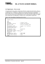
Example: Suppose a user connects a wind speed sensor (anemometer) to the digital input, and this
sensor generates a pulse with a frequency of 13 Hz. So, every second, the sensor has generated 13
pulses. Now the sample interval was set to 5 seconds. What happens is this: The data logger will count
all pulse, and update the counter value every 5 seconds. So, the user has every 5 seconds a new data
value.
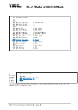
4.12.2 Port mode
This defines the electrical behaviour of the input (pull up / pull down)
4.12.2.1
Pull up
In this mode, a resistor is connected (from the input) to the positive rail of the internal power supply. So, in
order to create an event, the external device must pull the input to the ground. So, use this mode when
you have a “negative switching” sensor. (a device that switches to ground and has no voltage to drive the
port, e.g. a tipping bucket rain gauge)
4.12.2.2
Pull down
In this mode, a resistor is connected (from the input) to the ground of the data logger. So, in order to
create an event, the external device must drive the input with a positive voltage. So, use this mode when
you have a “positive switching” device. (a device that drives the data logger’s input with a voltage)
4.12.3 Register mode
Here you choose if the logger should register into the flash memory each single pulse, or units, which can
consist out of hundreds of pulses. Mostly you use Pulse, because most digital sensors like rain gauge are
generating at max speed 1 or a few pulses per second. If you use for instance a flow meter, or
anemometer that generates multiple pulses per second, and a completed unit in a few seconds, its high
frequency and you should use unit as a register mode, or else the logger could not keep up the speed to
write all the individual pulses to the flash memory.
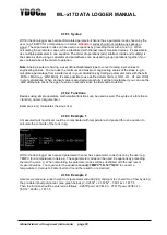
4.12.4 Anti-bounce filter
If your pulse giver is not bounce free, you may suppress unwished counts by enabling a bounce-filter.
Appling the bounce-filter will as a consequence limit the max count frequency to about 250Hz.
4.12.5 Units per pulse, or pulses per unit
Factor for transforming input pulses to real-life unit values. It depends on register mode setting.
4.12.6 Register value
Sometimes you like the counter to start from an existing value (perhaps the counter value of an electricity
meter you just connect?) Here you enter the initial value the counter must start with. This value is updated
when a pulse or unit (depends on register mode) is measured on the input, so each time you consult this
menu, this setting will be accurate automatically.
4.12.7 Register Reset
User can select if he wants the counter value to be reset at midnight, or that the counter is always
incrementing (32 bits).


