


ML-x17 DATA LOGGER MANUAL
Manufacturers of low power instruments
page 37
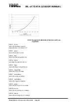
4. Perform a 1 point calibration (See chapter: Analog inputs
– Determine linear offset). For
the calibration point enter the expected physical value when the sensor output signal is
zero. (e.g. 0W/m2 for a pyranometer).
4.9.2 ML-OI-AD-PT1000
This board provides two PT1000 temperature sensor inputs using a
“bridge of wheatsone” to accurately
measure the resistance. Because sensing is resistance based any deviations in resistance in the loop will
affect the reading. Cable resistance can be ruled out by using 3 wires instead of 2 and setting the board
jumpers accordingly.
4.9.2.1
Calibration
As temperature vs resistance is rather linear you can, after determining the difference between the real
temperature and measured temperature, specify a temperature offset in the parameter settings.
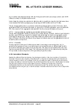
4.9.3 ML-OI-AX (Auxiliary inputs)
These boards are equipped with their own processor running their own firmware to do specific signal
processing or data acquisition on their inputs and providing the results as additional input channels to the
data logger. Most boards are having a
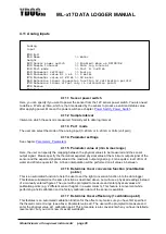
‘Terminal’-interface for testing/configuration that can be accessed
thru the
‘Terminal’-interface of the data logger. There are boards available to add additional counters,
digital thermometers, humidity sensors etc.
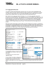
4.9.4 ML-OO (Auxiliary outputs)
These boards are equipped with their own processor running their own firmware to do specific signal
processing or data publishing on their outputs. A board can have up to 32 channels that can be regularly
updated with parameters from the data logger, parameters with their data output flags" set to the
concerned auxiliary output board. The order in which parameters are provided to the board follows the
order of parameters as organized through the "Parameter overview"-menu of the data logger. There are
boards available to add additional output switches, publishing parameters thru MODBUS/RTU, etc.
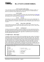
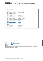
4.10 Internal Sensors
The data logger is equipped with “internal sensors” in order to provide an insight in the status of the
system. We strongly recommend using this feature, because it tells you whether a system is running OK
or that a problem may arise in the near future (e.g. battery status)
4.10.1 Name
Name of this driver. Default is “internal” may be edited.
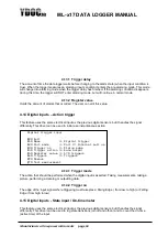
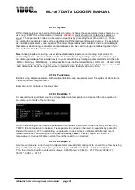
4.10.2 Sample interval
The sample interval of the internal driver. Default is same as data log interval. When a user like to have
fresh data while using USB, he can adjust it to a higher rate. More on intervals see chapter:
Principle of
Operation_Principle_of_Operation
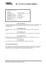
4.10.3 Battery Capacity
Used for keeping track of the remaining battery capacity. The users here define the capacity of the new
battery placed.


