22
|
eSC S1-X
–
User manual
6)
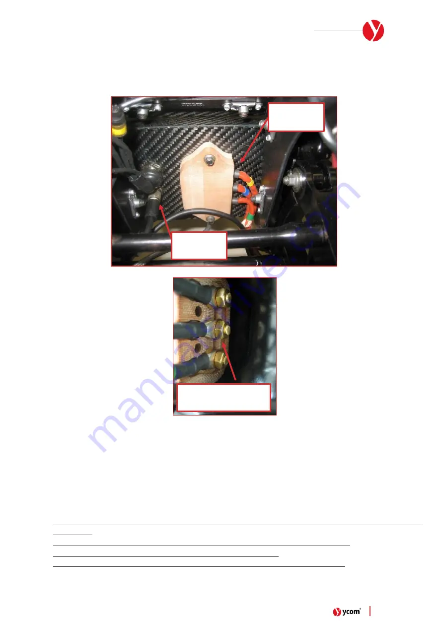
Remove the MGU wiring insulator cover positioned on the rear closing plate of the chassis
7)
Disconnect the N°3 Motor Phase cable. To disconnect the Motor Phase cable, use a N°10 Wrench tool and remove
the brass nut, the brass washer, and the phase cable connector.
8)
Disconnect the Motor Signal cable from the rear closing plate of the chassis
Image 10
- MGU Phase cable & signal connector
9)
Now it is possible to remove completely the rear motor assembly from the vehicle and proceed with one of the
maintenances (Brake disc change, Tyre change, Motor change)
10)
Re-assembly everything following the above instruction in the opposite way. When positioning the Motor into the
rear forks, be careful about the correct positioning of the N°2 centering bushes on the Motor Axis. To facilitate
insertion of the motor inside the housing, you can help yourself with the help of a rubber hummer.
NB:
•
Pay attention on the motor phase order. Remember to install no. 2 copper washer between all the nuts and
connectors.
•
When disassemble the MGU please be careful during this operation due to voltage hazard.
•
When disassemble the MGU check the tightness of the copper studs.
•
At the end of the day also check the tightness of the copper studs/nuts inside the chassis
MGU Phase
wirings
MGU Signal
connector
Brass M6 nut + N°2 wave
brass washer each side
Summary of Contents for eSC S1-X
Page 1: ...1 eSC S1 X User manual eSC S1 X User Manual TEAMS v2 03 05 2022...
Page 4: ...4 eSC S1 X User manual Image 1 Full Vehicle main views 1 eSC S1 X Vehicle Views...
Page 12: ...12 eSC S1 X User manual Image 2 Standard Setup for Front Fork assembly...
Page 13: ...13 eSC S1 X User manual Image 3 Standard Setup for Rear Fork assembly...
Page 14: ...14 eSC S1 X User manual Image 4 Standard Steering Damper Setup...
Page 18: ...18 eSC S1 X User manual Image 6 Sequence for adjust the steering bearing preload 2 3 4 5 6...
Page 40: ...40 eSC S1 X User manual Image 22 Datalogger main screen...


