2.6 Connection of Welding Voltage Detecting Line
2-7
HW0480311
HW0480311
4.
Grounding
Ground terminal is provided at the input voltage terminal in the partition board of the
welding source for safe operation. Connect the grounding cable of 14 mm
2
or more to
the crimp contact. Ground resistance must be 100
Ω
or less.
Be sure to ground the base metal at resistance of 100
Ω
or less individually as shown
in " Fig. 2 Connection Diagram of Welding Source at Front Face ". If it is not
grounded, voltage may be generated in the base metal resulting in electric shock.
Make sure that the grounding is always done individually, separated from grounding for
the manipulator. Also, connect the welding source and the base metal with exclusive-
use base metal cable.
2.6
Connection of Welding Voltage Detecting Line
In the connection of the welding voltage detecting line, Be sure to observe the following items
.If the following items are not observed, the amount of the spatter generation might increase.
1.
Connect the welding voltage detecting line as close to the position where welding is
performed as possible.
2.
The welding voltage detecting line and the welding output cable must separate as far
as possible.(The distance is required 100mm or more.)
3.
When you use MOTOPOS(external welding positioner), Connect the welding voltage
detecting line with with the screw of the cover that exists in the base of MOTOPOS.
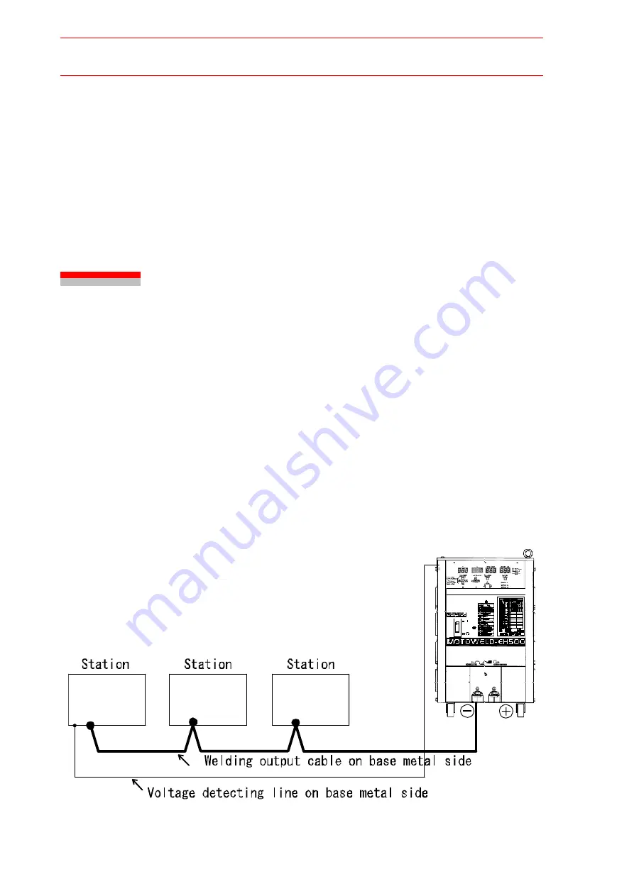
When two or more stations are used, connect the welding voltage detecting line with a station
as far away from the welding source as possible as indicated in " Fig. 2 Connection of Weld-
ing Voltage Detecting Line when Multiple Stations are Used ".
Fig. 2 Connection of Welding Voltage Detecting Line when Multiple Stations are Used
24/129


