14.2 Procedure of External Resistance Calibration
14-7
HW0480311
HW0480311
2.
Change the parameter that sets calibration of external resistance to "enabled" as fol-
lows:
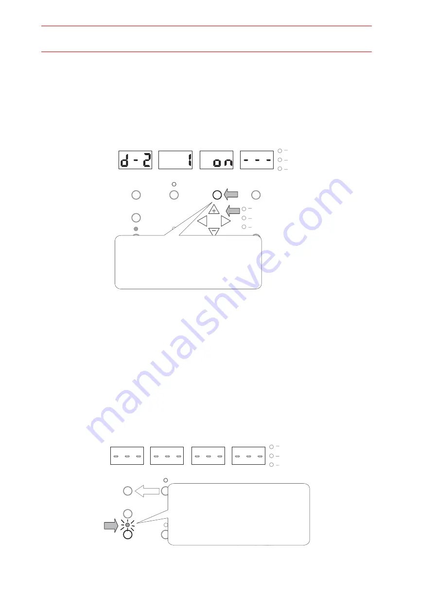
(1) Press the "PRM Set" button twice and the display "oFF" starts blinking.
(2) While the display is blinking, press the "+" button to change the display from "oFF"
to "on".
When the 7-segment LED indicator displays "on," the calibration for the external
resistance becomes valid.
Fig. 28 D Parameter Setting
(3) Press the "PRM Select" button once to return to the standby status.
3.
Save the setting as follows:
(1) Press the "Record" button for three seconds or more. The LED indicator lamp
above the "Record" button changes from flashing to lit, and the 7-segment LED indi-
cators display dashes.
(2) When the7-segment LED indicators are lit and the LED indicator lamp above the
"Record" button is turned OFF, the data on the set parameter are saved.
If the set parameters are not saved, the set data will be deleted with the main power
supply OFF.
Fig. 29 Saving the Setting
V
A
Wire m/min
Type
Record
20
Gas
Common PRM Select
PRM Select
PRM Set
Weld,Type
File No.1
File No.2
File No.3
User File Select
Power
Warning
Search
L
R
Press the "PRM Set" button twice so that
the "OFF" display blinks. Then press "+" button
to change the setting of parameter "d-2 1" to
"on" from "OFF".
After the setting change, press "PRM Select" to
return to the stadby status.
V
A
Wire m/min
Type
Record
Gas
Common PRM Select
PRM Select
PRM Set
Weld,Type
File No.1
File No.2
File No.3
User File Select
Power
Warning
Search
L
R
V/Set
A.W/S
Pressing of the "Record" button for three seconds
or more changes the LED indicator lamp above the
"Record" button from flashing to lit, and the
7-segment LED indicators display dashes.
When the 7-segment LED indicators return to the
normal standby status and the LED indicator lamp
above the "Record " button is turned OFF, the data
on changed setting are all saved.
110/129


