


Here you activate respectively deactivate the diagnostic interrupt function. With a set
diagnostic interrupt bit in case of an error a diagnostic interrupt message is sent to the
upper master system. There the diagnostics message can further be processed. More
may be found in the manual of the master system.
n
With the
channel activation
channel groups may be activated or deactivated. With
channel activation
= 1 the corresponding channel group is in "standard operation".
n
Deactivated channel groups (
channel activation
= 0) permanently provide a logical 0
as output signal, independent from the defined signal of the safety PLC. This can be
useful during the first start-up.
NOTICE!
Deactivation of channel groups represents a potentially dangerous condi-
tion!
Here you can specify for each channel group, if the outputs of the safety output module
are controlled by the safety PLC individually (
1-channel
) or in pairs (
2-channel
). The
paired control option simplifies the creation of the safety logic in the safety PLC. Please
consider that regardless of the type of the activation mode, in the System SLIO safety
module, each output is always 2-channel driven and switched off (double PP switching).
n
With
1-channel
1 or 2 actuators with one input are connected to one channel. Here
respectively one bit is used to control an output. By means of 2-channel actuators, a
higher safety level like SIL3 or PLe can be achieved, if you can exclude the errors
cross-circuit or external power supply or there is a superior shut-down on error.
n
With
2-channel
a 2-channel actuator with 2 inputs or 2 actuators with respectively 1
input are connected to a channel group. Here bit 0 switches the outputs DO 0 and DO
1 respectively bit 2 switches the outputs DO 2 and DO 3. Here the actuator / actua-
tors get the output signal via both channels. Errors in cross circuits and external
power supply at the channel group can be identified and controlled, if this relates to
only one of the two lines. This enables to achieve higher safety levels like SIL 3 and
PLe.
Chap. 3.7.2 ‘Connection examples for digital safety outputs’ page 96
NOTICE!
In case of error with a switched-off output, a short-time turn-on pulse with
a max. length of the error detection time can occur.
The error detection time is 6ms + 2 x
test pulse length
.
If this parameter is set, the System SLIO safety module observes the outputs with output
state "1", whether there is a min. current of 10mA...30mA. By this way a line break can be
detected. Here the System SLIO safety module gets to fail-safe state and the outputs are
switched off.
CAUTION!
This function must not be used as safety function. This means a safety
function must not depend on this function.
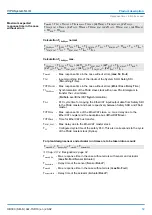
Activation diagnostic
interrupt
Channel activation
Activation mode
Wire break detection
VIPA System SLIO
Product description
SDO 4xDC 24V 0.5A - FSoE Parameter record set > FSoE application parameters
HB300 | SM-S | 02x-1SD10 | en | 20-02
52


