Programming 176
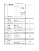
Analog Inputs
H3-01
Terminal A1 Signal Level
Selection
Term A1 Lvl Sel
Sets the signal level of terminal A1.
0: 0 to 10Vdc
1: -10 to +10Vdc
0 to 1
0
A
A
A
A
H3-02
Terminal A1 Gain Setting
Terminal A1 Gain
Sets the output level when 10V is input, as a percentage of the
maximum output frequency (E1-04).
0.0 to
1000.0
100.0%
A
A
A
A
H3-03
Terminal A1 Bias Setting
Terminal A1 Bias
Sets the output level when 0V is input, as a percentage of the
maximum output frequency (E1-04).
–100.0
to
+100.0
0.0%
A
A
A
A
H3-04
Terminal A3 Signal Level
Selection
Term A3 Signal
Sets the signal level of terminal A3.
0: 0 to 10Vdc
1: -10 to +10Vdc
0 to 1
0
A
A
A
A
H3-05
Terminal A3 Function
Selection
Terminal A3 Sel
Selects the function of terminal A3.
0: Frequency
Bias
100% = Maximum output frequency (E1-04)
1: Frequency Reference Gain (FGAIN)
100% = Frequency reference command value A1
Total gain = Internal gain (H3-02) x FGAIN
2: Aux Frequency Reference 1
Used in conjunction with multi-function inputs “multi-step
frequency reference 1-4” (d1-16).
100% = Maximum output frequency (E1-04)
3: Aux Frequency Reference 2
Used in conjunction with multi-function inputs “multi-step
frequency reference 1-4” (d1-16).
100% = Maximum output frequency (E1-04)
4: Output Voltage Bias
100% = Motor rated voltage (E1-05).
Voltage boost after V/F pattern.
5: Accel / Decel Time Coefficient
100% = Active accel / decel time (C1-01 thru C1-08)
6: DC Injection Braking Current
100% = Drive rated current.
Parameter b2-02 is disabled.
7: Overtorque / Undertorque Detection Level
Used for multi-function digital output for
“overtorque/undertorque”.
100% = motor rated torque (OLV, FV) or Drive rated current
(V/F, V/F w/PG).
Internal overtorque detection level (C6-02) disabled.
8: Stall Prevention Level During Run
100% = L3-06.
9: Frequency Reference Lower Limit
100% = Maximum output frequency (E1-04).
Either d2-02 setting or A3 input level, whichever is greater,
becomes effective.
A: Jump Frequency 4
100% = Maximum output frequency (E1-04).
B: PID Feedback
100% = Maximum output frequency (E1-04).
C: PID Set Point
100% = Maximum output frequency (E1-04).
Frequency reference no longer acts as a PID setpoint.
D: Frequency Reference Bias 2 (FBIAS2)
100% = Maximum output frequency (E1-04).
Total bias = Internal bias (H3-03) + FBIAS (H3-07) + A3 input
level
E: Motor Temperature
See parameters L1-03 & L1-04.
10: FWD Torque Limit (Quadrant 1)
100% = Motor rated torque.
11: REV Torque Limit (Quadrant 3)
100% = Motor rated torque.
12: Regenerative Torque Limit (Quadrants 2 and 4)
100% = Motor rated torque.
13: Torque Reference (in Torque Control); Torque Limit (in Speed
Control) (Quadrants 1, 2, 3, 4)
100% = Motor rated torque.
14: Torque Compensation
100% = Motor rated torque.
15: FWD / REV Torque Limit (Quadrants 1 and 3)
100% = Motor rated torque.
1F: Not Used
0 to 1F
2
A
A
A
A
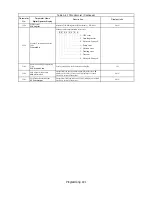
Denotes that parameter can be changed when the Drive is running.Note: Some analog inputs are control method dependent.
Table A.1 F7 Parameter List (Continued)
Parameter
No.
Parameter Name
Digital Operator Display
Description
Setting
Range
Factory
Setting
Control Method
V/F
V/F
w/
PG
Open
Loop
Vector
Flux
Vector
Summary of Contents for Varispeed f7
Page 1: ...F7 Drive Programming Manual Model CIMR F7U Document Number TM F7 02...
Page 2: ......
Page 8: ...vi Notes...
Page 158: ...Programming 150 Notes...


